Page 4103 of 4770
SFI SYSTEM
SF±3
1502 Author�: Date�:
(b) When connecting the union bolt on th")
S05054
New Gasket
FI1654
Fulcrum Length
30 cm
SST
FI6372 FI6372
New O±Ring
Grommet
InjectorCORRECT
WRONG
± SFI (1MZ±FE)SFI SYSTEM
SF±3
1502 Author�: Date�:
(b) When connecting the union bolt on the high pressure pipe
union, observe these procedures:
(1) Always use 2 new gaskets.
(2) Tighten the union bolt by hand.
(3) Tighten the union bolt to the specified torque.
Torque: 32.5 N´m (330 kgf´cm, 24 ft´lbf)
(c) When connecting the flare nut on the high pressure pipe
union, observe these procedures:
(1) Apply a light coat of engine oil to the flare nut, and
tighten the flare nut by hand.
(2) Using SST, tighten the flare nut to specified torque.
SST 09631±22020
NOTICE:
Do not rotate the fuel pipe, when tightening the flare nut.
Torque: 28 N´m (285 kgf´cm, 21 ft´lbf) for using SST
HINT:
Use a torque wrench with a fulcrum length of 30 cm (11.81 in.).
(d) Observe these precautions when removing and installing
the injectors.
(1) Never reuse the O±ring.
(2) When placing a new O±ring on the injector, take
care not to damage it in any way.
(3) Coat a new O±ring with spindle oil or gasoline be-
fore installing±never use engine, gear or brake oil.
Page 4104 of 4770
SFI")
B00630
O±Ring
Grommet
Spacer InsulatorDelivery Pipe California A/T
Except California A/TO±Ring
O±Ring
Grommet
Spacer InsulatorDelivery Pipe
O±Ring
S04583
S05040
Vinyl Bag SF±4
± SFI (1MZ±FE)SFI SYSTEM
1503 Author�: Date�:
(e) Install the injector to the delivery pipe and intake manifold,
as shown in the illustration.
Before installing the injector, must apply spindle oil or gas-
oline on the place where a delivery pipe or an intake man-
ifold touches an O±ring of the injector.
(f) Observe these precautions when disconnecting the fuel
tube connector (quick type).
(1) Check if there is any dirt like mud on the pipe and
around the connector before disconnecting them
and clean the dirt away.
(2) Be sure to disconnect with hands.
(3) When the connector and the pipe are stuck, pinch
the retainer between the hands, push and pull the
connector to free to disconnect and pull it out. Do
not use any tool at this time.
(4) Inspect if there is any dirt or the likes on the seal sur-
face of the disconnected pipe and clean it away.
(5) Prevent the disconnected pipe and connector from
damaging and mixing foreign objects by covering
them with a vinyl bag.
Page 4105 of 4770
SFI SYSTEM
SF±5
1504 Author�: Date�:
(g) Observe these precautions when connecting the fuel
tube connector (quick ty")
S05382
Retainer
S05050
Click Sound
S05358
TOYOTA
Hand±Held Tester
± SFI (1MZ±FE)SFI SYSTEM
SF±5
1504 Author�: Date�:
(g) Observe these precautions when connecting the fuel
tube connector (quick type).
(1) Do not reuse the retainer removed from the pipe.
(2) Must use hands without using tools when to remove
the retainer from the pipe.
(3) Check if there is any damage or foreign objects on
the connected part of the pipe.
(4) Match the axis of the connector with axis of the pipe,
and push in the connector until the retainer makes
a ºclickº sound. In case that the connections is tight,
apply little amount of new engine oil on the tip of the
pipe.
(5) After having finished the connection, check if the
pipe and the connector are securely connected by
pulling them.
(6) Check if there is any fuel leakage.
(h) Observe these precautions when handling nylon tube.
(1) Pay attention not to turn the connected part of the
nylon tube and the quick connector with force when
connecting them.
(2) Pay attention not to kink the nylon tube.
(3) Do not remove the EPDM protector on the outside
of the nylon tube.
(4) Must not close the piping with the nylon tube by
bending it.
(i) Check that there are no fuel leaks after doing mainte-
nance anywhere on the fuel system.
(1) Connect a TOYOTA hand±held tester to the DLC3.
(2) Turn the ignition switch ON and push the TOYOTA
hand±held tester main switch ON.
NOTICE:
Do not start the engine.
(3) Select the active test mode on the TOYOTA hand±
held tester.
(4) Please refer to the TOYOTA hand±held tester oper-
ator 's manual for further details.
(5) If you have no TOYOTA hand±held tester, connect
the positive (+) and negative (±) leads from the bat-
tery to the fuel pump connector.
(See page SF±6)
(6) Check that there are no leaks from any part of the
fuel system.
(7) Turn the ignition switch to LOCK.
(8) Disconnect the TOYOTA hand±held tester from the
DLC3.
Page 4108 of 4770
FUEL PUMP
1507 Author�: Date�:
(p) After checking fuel pressure, disconnect the negative (±)
terminal cable")
S05351
S06086
Fuel Hose
Clamp
S04508
Ohmmeter
4 5
S04509
4 5
Battery SF±8
± SFI (1MZ±FE)FUEL PUMP
1507 Author�: Date�:
(p) After checking fuel pressure, disconnect the negative (±)
terminal cable from the battery and carefully remove the
SST and fuel tube connector to prevent gasoline from
splashing.
SST 09268±41047, 09268±41250, 09268±45012
(q) Reconnect the No.1 fuel pipe (fuel tube connector).
CAUTION:
Perform connecting operations of the fuel tube connector
(quick type) after observing the precautions.
(See page SF±1)
(r) Surely install the fuel hose clamp to the fuel filter with
ºclickº sound.
(s) After installing the clamp, check that the clamp is fixed by
pulling up the clamp.
(t) Reconnect the negative (±) terminal cable to the battery.
(u) Check for fuel leaks.
3. REMOVE REAR SEAT CUSHION
4. REMOVE FLOOR SERVICE HOLE COVER
5. DISCONNECT FUEL PUMP & SENDER GAUGE
CONNECTOR
6. INSPECT FUEL PUMP RESISTANCE
Using an ohmmeter, measure the resistance between terminals
4 and 5.
Resistance: 0.2 ± 3.0 W at 20°C (68°F)
If the resistance is not as specified, replace the fuel pump.
7. INSPECT FUEL PUMP OPERATION
Connect the positive (+) lead from the battery to terminal 4 of
the connector, and the negative (±) lead to terminal 5. Check
that the fuel pump operates.
NOTICE:
�These tests must be done quickly (within 10 seconds)
to prevent the coil burning out.
�Keep the fuel pump as far away from the battery as
possible.
�Always do the switching at the battery side.
Page 4128 of 4770
SF07M±04
B00629
California A/T
Except California A/TNew Insulator
New Grommet New
O±RingNew
O±Ring
New Grommet
New Insulator
New
O±RingNew
O±Ring
B00625
Turn
Connector
Push
Turn
Connector
Push
California A/T
Except California A/T
S04510
Spacer
Spacer SF±28
± SFI (1MZ±FE)INJECTOR
1527 Author�: Date�:
INSTALLATION
1. INSTALL INJECTORS AND DELIVERY PIPES
(a) Install new insulator and grommet to each injector.
(b) Apply a light coat of spindle oil or gasoline to 2 new O±
rings and install them to each injector.
(c) Apply a light coat of spindle oil or gasoline on the place
where a delivery pipe touches an O±ring of the injector.
(d) While turning the injector clockwise and counterclock-
wise, push it to the delivery pipes. Install the 6 injectors.
(e) Position the injector connector outward.
(f) Place the 4 spacers in position on the intake manifold.
Page 4129 of 4770
INJECTOR
SF±29
1528 Author�: Date�:
(g) Apply a light coat of spindle oil or gasoline on the place
where a intake manifold touc")
B01021
S04728
Rotate
Outward
B01020
S06525
Align
S05351
± SFI (1MZ±FE)INJECTOR
SF±29
1528 Author�: Date�:
(g) Apply a light coat of spindle oil or gasoline on the place
where a intake manifold touches an O±ring of the injector.
(h) Place the delivery pipes and fuel pipe together with the 6
injectors in position on the intake manifold.
(i) Temporarily install the 4 bolts holding the delivery pipes
to the intake manifold.
(j) Temporarily install the bolt holding the No.1 fuel pipe to
the intake manifold.
(k) Check that the injectors rotate smoothly.
HINT:
If injectors do not rotate smoothly, the probable cause is incor-
rect installation of O±rings. Replace the O±rings.
(l) Position the injector connector outward.
(m) Tighten the 4 bolts holding the delivery pipes to the intake
manifold.
Torque: 10 N´m (100 kgf´cm, 7 ft´lbf)
(n) Tighten the bolt holding the No.1 fuel pipe to the intake
manifold.
Torque: 19.5 N´m (200 kgf´cm, 14 ft´lbf)
2. CONNECT NO.1 FUEL PIPE
(a) Align the alignment marks (white paint) on the No.1 fuel
pipe.
(b) Connect the No.1 fuel pipe (fuel tube connector) to the
fuel filter.
CAUTION:
Perform connecting operations of the fuel tube connector
(quick type) after observing the precaution.
(See page SF±1)
Page 4142 of 4770
IDLE AIR CONTROL (IAC) VALVE
1541 Author�: Date�:
IDLE AIR CONTROL (IAC) VALVE
ON±VEHICLE INSPECTION
1. INSPECT")
SF07Y±03
S04529
E1DLC1
SST
TE1
DLC1
S04533
RSC
+B
RSO
Ohmmeter SF±42
± SFI (1MZ±FE)IDLE AIR CONTROL (IAC) VALVE
1541 Author�: Date�:
IDLE AIR CONTROL (IAC) VALVE
ON±VEHICLE INSPECTION
1. INSPECT IAC VALVE OPERATION
(a) Initial conditions:
�Engine at normal operating temperature
�Idle speed checked correctly
�Transmission in neutral position
�A/C switch OFF
(b) Using SST, connect terminals TE1 and E1 of the
DLC1.
SST 09843±18020
(c) After engine speed is kept at approx. 1,000 rpm for 5 se-
conds, check that it returns to idle speed.
If the engine speed operation is not as specified, check the IAC
valve, wiring and ECM.
(d) Remove the SST from the DLC1.
SST 09843±18020
2. INSPECT IAC VALVE RESISTANCE
NOTICE:
ºColdº and ºHotº in the following sentences express the
temperature of the coils themselves. ºColdº is from ±10°C
(14°F) to 50°C (122°F) and ºHotº is from 50°C (122°F) to
100°C (212°F).
(a) Disconnect the IAC valve connector.
(b) Using an ohmmeter, measure the resistance between ter-
minal +B and other terminals (RSC, RSO).
Resistance:
Cold17.0 ± 25.0 W
Hot21.5 ± 29.5 W
If resistance is not as specified, replace the IAC valve.
(c) Reconnect the IAC valve connector.
3. INSPECT AIR ASSIST SYSTEM
(a) Initial conditions:
�Engine at normal operating temperature
�Idle speed checked correctly
�Transmission in neutral position
�A/C switch OFF
Page 4152 of 4770
SF087±03
B06468
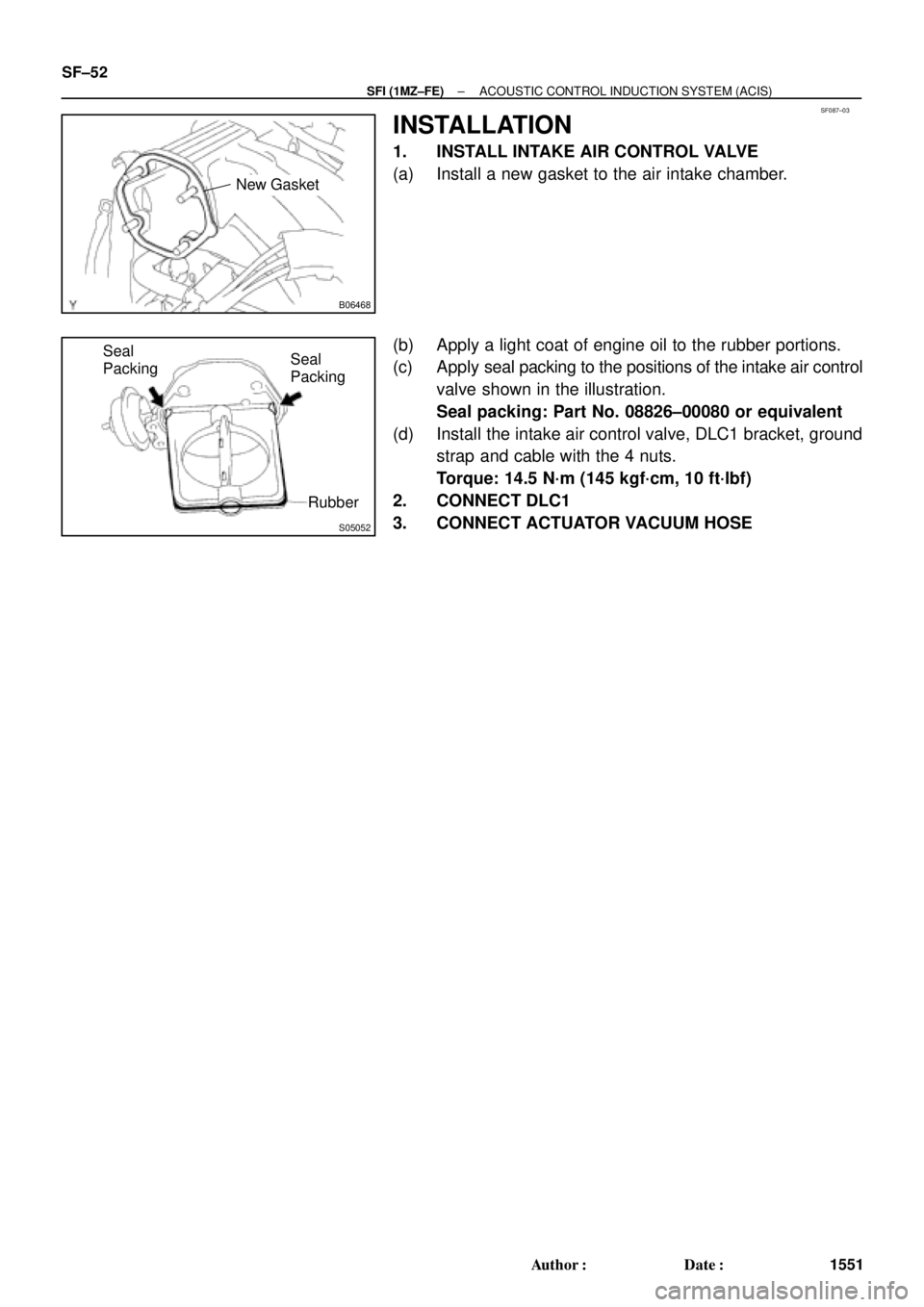
New Gasket
S05052
Seal
Packing
Rubber Seal
Packing SF±52
± SFI (1MZ±FE)ACOUSTIC CONTROL INDUCTION SYSTEM (ACIS)
1551 Author�: Date�:
INSTALLATION
1. INSTALL INTAKE AIR CONTROL VALVE
(a) Install a new gasket to the air intake chamber.
(b) Apply a light coat of engine oil to the rubber portions.
(c) Apply seal packing to the positions of the intake air control
valve shown in the illustration.
Seal packing: Part No. 08826±00080 or equivalent
(d) Install the intake air control valve, DLC1 bracket, ground
strap and cable with the 4 nuts.
Torque: 14.5 N´m (145 kgf´cm, 10 ft´lbf)
2. CONNECT DLC1
3. CONNECT ACTUATOR VACUUM HOSE