Page 2826 of 4770

641 Author�: Date�:
2. Chapter 2: On±Vehicle Repair
(�: A140E AUTOMATIC TRANSAXLE Repair Manual Pub. No. RM385U)
SymptomSuspect AreaSee page
Vehicle")
DI±406
± DIAGNOSTICSAUTOMATIC TRANSAXLE (A140E)
641 Author�: Date�:
2. Chapter 2: On±Vehicle Repair
(�: A140E AUTOMATIC TRANSAXLE Repair Manual Pub. No. RM385U)
SymptomSuspect AreaSee page
Vehicle does not move in any forward positions and reverse posi-
tion
1. Manual valve
2. Throttle valve
3. Primary regulator valve
4. Off±vehicle repair matrix chart�
�
�
±
Vehicle does not move in R position1. Off±vehicle repair matrix chart±
No up±shift (1st " 2nd)1. 1±2 shift valve
2. Off±vehicle repair matrix chart�
±
No up±shift (2nd " 3rd)1. 2±3 shift valve
2. Off±vehicle repair matrix chart�
±
No up±shift (3rd " O/D)1. 3±4 shift valve
2. Off±vehicle repair matrix chart�
±
No down±shift (O/D " 3rd)1. 3±4 shift valve�
No down±shift (3rd " 2nd)1. 2±3 shift valve�
No down±shift (2nd " 1st)1. 1±2 shift valve�
No lock±up or No lock±up off1. Lock±up relay valve
2. Off±vehicle repair matrix chart�
±
Harsh engagement (N " D)1. C1 accumulator
2. Off±vehicle repair matrix chart�
±
Harsh engagement (N " R)1. C2 accumulator
2. Off±vehicle repair matrix chart�
±
Harsh engagement (N " L)1. Low coast modulator valve�
Harsh engagement (Lock±up)1. Lock±up relay valve
2. Off±vehicle repair matrix chart�
±
Harsh engagement (1st " 2nd " 3rd " O/D)
1. Throttle modulator valve
2. Cut back valve
3. Throttle valve�
�
�
Harsh engagement (2nd " 3rd)1. C2 accumulator�
Harsh engagement (3rd " O/D)1. B0 accumulator�
Harsh engagement (O/D " 3rd)1. C0 accumulator
2. B
0 accumulator
�
�
Slip or shudder (Forward and reverse)
1. Throttle valve
2. Oil strainer
3. Off±vehicle repair matrix chart�
�
±
No engine braking (1st: L position)1. Low coast modulator valve
2. Off±vehicle repair matrix chart�
±
No engine braking (2nd: 2 position)1. 2nd coast modulator valve
2. Off±vehicle repair matrix chart�
±
No kick±down
1. 1±2 shift valve
2. 2±3 shift valve
3. 3±4 shift valve�
�
�
Page 2831 of 4770

DI±411
646 Author�: Date�:
DTC P0750, P0755 Shift Solenoid A/B Malfunction
(Shift Solenoid Valve No.1/No.2)
SYSTEM DESCRIPTION
The ECM uses signals fr")
Q07741
± DIAGNOSTICSAUTOMATIC TRANSAXLE (A140E)
DI±411
646 Author�: Date�:
DTC P0750, P0755 Shift Solenoid A/B Malfunction
(Shift Solenoid Valve No.1/No.2)
SYSTEM DESCRIPTION
The ECM uses signals from the vehicle speed sensor and crankshaft position sensor to detect the actual
gear position (1st, 2nd, 3rd or O/D gear).
Then the ECM compares the actual gear with the shift schedule in the ECM memory to detect mechanical
trouble of the shift solenoid valves, valve body or automatic transaxle (clutch, brake or gear etc.).
DTC No.DTC Detecting ConditionTrouble Area
P0750
P0755During normal driving, the gear required by the ECM does not
match the actual gear
(2 trip detection logic)�Shift solenoid valve No.1/No.2 is stuck open or closed
�Valve body is blocked up or stuck
�Automatic transaxle (clutch, brake or gear etc.)
Check the shift solenoid valve No.1 when DTC P0750 is output and check the shift solenoid valve No.2 when
DTC P0755 is output.
INSPECTION PROCEDURE
1 Check shift solenoid valve No.1 or No.2 operation.
PREPARATION:
(a) Remove the oil pan.
(b) Remove the shift solenoid valve No.1 or No.2.
CHECK:
(a) By applying 490 kPa (5 kgf/cm2, 71 psi) of compressed
air, check that the solenoid valve does not leak air.
(b) When battery positive voltage is supplied to the shift sole-
noid valve, check that the valve opens.
OK:
(a) Solenoid valve does not leak air.
(b) Solenoid valve opens.
NG Replace the shift solenoid valve No.1 or No.2.
OK
DI032±02
Page 2836 of 4770
Q07744
DI±416
± DIAGNOSTICSAUTOMATIC TRANSAXLE (A140E)
651 Author�: Date�:
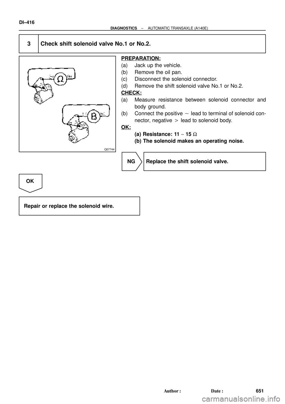
3 Check shift solenoid valve No.1 or No.2.
PREPARATION:
(a) Jack up the vehicle.
(b) Remove the oil pan.
(c) Disconnect the solenoid connector.
(d) Remove the shift solenoid valve No.1 or No.2.
CHECK:
(a) Measure resistance between solenoid connector and
body ground.
(b) Connect the positive � lead to terminal of solenoid con-
nector, negative � lead to solenoid body.
OK:
(a) Resistance: 11 ~ 15 W
(b) The solenoid makes an operating noise.
NG Replace the shift solenoid valve.
OK
Repair or replace the solenoid wire.
Page 2837 of 4770

DI±417
652 Author�: Date�:
DTC P0770 Shift Solenoid E Malfunction
(Shift Solenoid Valve SL)
SYSTEM DESCRIPTION
The EC")
Q07745
Drain
Drain Line
Pressure
Q07746
± DIAGNOSTICSAUTOMATIC TRANSAXLE (A140E)
DI±417
652 Author�: Date�:
DTC P0770 Shift Solenoid E Malfunction
(Shift Solenoid Valve SL)
SYSTEM DESCRIPTION
The ECM uses the signals from the Throttle position sensor,
Air±flow meter and Crankshaft position sensor to monitor the
engagement condition of the lock±up clutch.
Then the ECM compares the engagement condition of the
lock±up clutch with the lock±up schedule in the ECM memory
to detect mechanical trouble of the shift solenoid valve SL,
valve body, torque converter clutch or automatic transaxle
(clutch, brake or gear etc.).
DTC No.DTC Detecting ConditionTrouble Area
P0770
�Lock±up does not occur when driving in the lock±up range
(normal driving at 80 km/h [50 mph]), or lock±up remains ON
in the lock±up OFF range.
(2 trip detection logic)
�When lock±up is ON, clutch or brake slips or gear is broken.�Shift solenoid valve SL is stuck open or closed
�Valve body blocked up or stuck
�Lock±up clutch
�Automatic transaxle (clutch, brake or gear etc.)
INSPECTION PROCEDURE
1 Check solenoid valve SL operation.
PREPARATION:
(a) Remove the oil pan.
(b) Remove the shift solenoid valve SL.
CHECK:
(a) By applying 490 kPa (5 kgf/cm2, 71 psi) of compressed
air, check that the solenoid valve does not leak air.
(b) When battery positive voltage is supplied to the shift sole-
noid valve, check that the solenoid valve opens.
OK:
(a) Solenoid valve does not leak air.
(b) Solenoid valve opens.
NG Replace the solenoid valve SL.
OK
DI034±02
Page 2842 of 4770
Q07749
DI±422
± DIAGNOSTICSAUTOMATIC TRANSAXLE (A140E)
657 Author�: Date�:
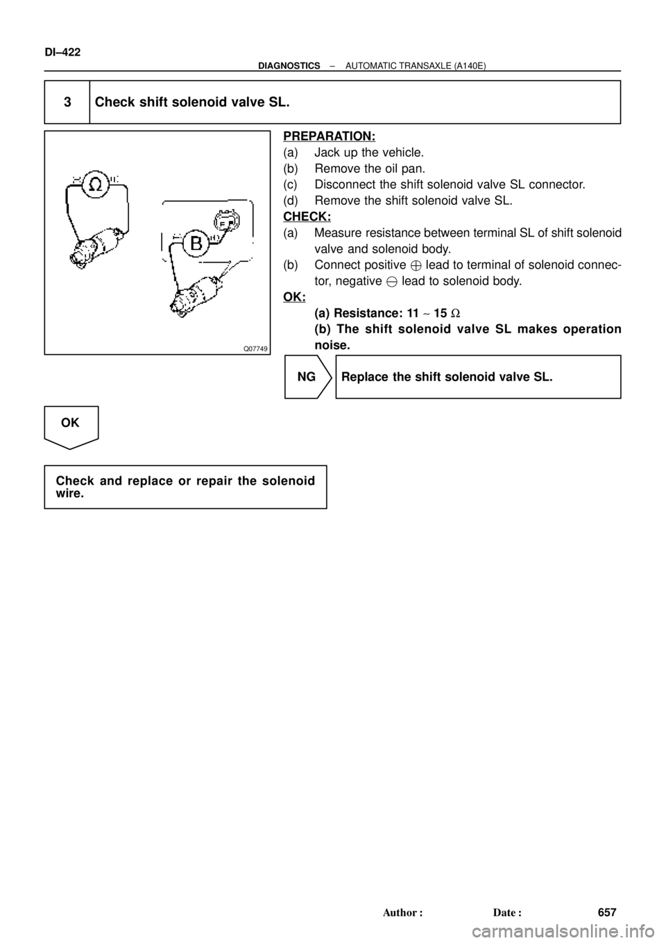
3 Check shift solenoid valve SL.
PREPARATION:
(a) Jack up the vehicle.
(b) Remove the oil pan.
(c) Disconnect the shift solenoid valve SL connector.
(d) Remove the shift solenoid valve SL.
CHECK:
(a) Measure resistance between terminal SL of shift solenoid
valve and solenoid body.
(b) Connect positive � lead to terminal of solenoid connec-
tor, negative � lead to solenoid body.
OK:
(a) Resistance: 11 ~ 15 W
(b) The shift solenoid valve SL makes operation
noise.
NG Replace the shift solenoid valve SL.
OK
Check and replace or repair the solenoid
wire.
Page 2864 of 4770
 DI±444
± DIAGNOSTICSAUTOMATIC TRANSAXLE (A541E)
679 Author�: Date�:
(c) Replace the ATF.
(1) Remove the drain plug and drain")
AT4657
AT8562
AT3417
OK if hot
Add if hot
AT4252
0 ~ 1 mm (0 ~ 0.04 in.) DI±444
± DIAGNOSTICSAUTOMATIC TRANSAXLE (A541E)
679 Author�: Date�:
(c) Replace the ATF.
(1) Remove the drain plug and drain the fluid.
(2) Reinstall the drain plug securely.
(3) With the engine OFF add new fluid through the oil
filler pipe.
Fluid type: ATF D±II or DEXRON®III (DEXRON®II)
Capacity: 3.9 liters (4.1 US qts, 3.4 Imp. qts)
(4) Start the engine and shift the shift lever into all posi-
tions from P to L position and then shift into P posi-
tion.
(5) With the engine idling, check the fluid level. Add
fluid up to the COOL level on the dipstick.
(6) Check the fluid level at the normal operating tem-
perature, 70 ± 80 °C (158 ± 176 °F), and add as
necessary.
NOTICE:
Do not overfill.
(d) Check the fluid leaks.
Check for leaks in the transaxle.
If there are leaks, it is necessary to repair or replace O±rings,
gasket, oil seals, plugs or other parts.
(e) Inspect and adjust the throttle cable.
(1) Check that the accelerator pedal is fully released.
(2) Check that the inner cable is not slack.
(3) Measure the distance between the outer cable end
and stopper on the cable.
Standard distance: 0 ± 1 mm (0 ± 0.04 in.)
If the distance is not the standard, adjust the cable by the ad-
justing nuts.
Page 2867 of 4770

DI±447
682 Author�: Date�:
7. HYDRAULIC TEST
Measure the line pressure
NOTICE:
�Do the test at normal operation fluid temperature 50 ± 80 °C (122 ± 176 °")
± DIAGNOSTICSAUTOMATIC TRANSAXLE (A541E)
DI±447
682 Author�: Date�:
7. HYDRAULIC TEST
Measure the line pressure
NOTICE:
�Do the test at normal operation fluid temperature 50 ± 80 °C (122 ± 176 °F).
�The line pressure test should always be carried out in pairs. One technician should observe
the conditions of wheels or wheel stoppers outside the vehicle while the other is doing the test.
�Be careful to prevent SST's hose from interfering with the exhaust pipe.
(1) Warm up the ATF.
(2) Remove the test plug on the transaxle case front left side and connect SST.
(See page AX±21 for the location to connect SST)
SST 09992±00095 (09992±00231, 09992±00271)
(3) Fully apply the parking brake and chock the 4 wheels.
(4) Connect an OBD II scan tool or TOYOTA hand±held tester to DLC3.
(5) Start the engine and check idling speed.
(6) Keep your left foot pressed firmly on the brake pedal and shift into D position.
(7) Measure the line pressure when the engine is idling.
(8) Depress the accelerator pedal all the way down. Quickly read the highest line pressure when
engine speed reaches stall speed.
(9) In the same manner, do the test in R position.
Specified line pressure:
ConditionD position kPa (kgf/cm2, psi)R position kPa (kgf/cm2, psi)
Idling401 ± 461 (4.1 ± 4.7, 58 ± 66)804 ± 882 (8.2 ± 9.0, 117 ± 128)
Stall1,138 ± 1,236 (11.6 ± 12.6, 165 ± 179)1,716 ± 1,854 (17.5 ± 18.9, 249 ± 269)
If the measured pressure is not up to specified value, recheck the throttle cable adjustment and retest.
Evaluation
ProblemPossible cause
If the measured values at all position are higher
�Throttle cable out of adjustment
�Throttle valve defective
�Regulator valve defective
If the measured values at all position are lower
�Throttle cable out of adjustment
�Throttle valve defective
�Regulator valve defective
�Oil pump defective
�O/D direct clutch defective
If pressure is low in the D position only�D position circuit fluid leakage
�Forward clutch defective
If pressure is low in the R position only
�R position circuit fluid leakage
�Direct clutch defective
�1st and reverse brake defective
Page 2874 of 4770

689 Author�: Date�:
2. Chapter 2: On±Vehicle Repair
(�: A541E AUTOMATIC TRANSAXLE Repair Manual Pub. No. RM530U)
SymptomSuspect AreaSee page
Vehicle")
DI±454
± DIAGNOSTICSAUTOMATIC TRANSAXLE (A541E)
689 Author�: Date�:
2. Chapter 2: On±Vehicle Repair
(�: A541E AUTOMATIC TRANSAXLE Repair Manual Pub. No. RM530U)
SymptomSuspect AreaSee page
Vehicle does not move in any forward position and reverse posi-
tion
1. Manual valve
2. Throttle valve
3. Primary regulator valve
4. Off±vehicle repair matrix chart�
�
�
DI±453
Vehicle does not move in R positionOff±vehicle repair matrix chartDI±453
No up±shift (1st " 2nd)1. 1±2 shift valve
2. Off±vehicle repair matrix chart�
DI±453
No up±shift (2nd " 3rd)1. 2±3 shift valve
2. Off±vehicle repair matrix chart�
DI±453
No up±shift (3rd " O/D)1. 3±4 shift valve
2. Off±vehicle repair matrix chart�
DI±453
No down±shift (O/D " 3rd)3±4 shift valve�
No down±shift (3rd " 2nd)2±3 shift valve�
No down±shift (2nd " 1st)1±2 shift valve�
No lock±up or No lock±up off1. Lock±up relay valve
2. Off±vehicle repair matrix chart�
DI±453
Harsh engagement (N " D)1. C1 accumulator
2. Off±vehicle repair matrix chart�
DI±453
Harsh engagement (N " R)
1. C2 accumulator
2. No.1 accumulator control valve
3. Off±vehicle repair matrix chart�
�
DI±453
Harsh engagement (N " L)Low coast modulator valve�
Harsh engagement (Lock±up)1. Lock±up relay valve
2. Off±vehicle repair matrix chart�
DI±453
Harsh engagement (1st " 2nd " 3rd " O/D)
1. Throttle modulator valve
2. Cut back valve
3. Throttle valve�
�
�
Harsh engagement (2nd " 3rd)C2 accumulator�
Harsh engagement (3rd " O/D)B0 accumulator�
Harsh engagement (O/D " 3rd)1. C0 accumulator
2. B
0 accumulator
�
�
Slip or shudder (Forward and reverse)
1. Throttle valve
2. Oil strainer
3. Off±vehicle repair matrix chart�
�
DI±453
No engine braking (1st: L position)1. Low coast modulator valve
2. Off±vehicle repair matrix chart�
DI±453
No engine braking (2nd: 2 position)1. 2nd coast modulator valve
2. Off±vehicle repair matrix chart�
DI±453
No kick±down
1. 1±2 shift valve
2. 2±3 shift valve
3. 3±4 shift valve�
�
�