Page 2880 of 4770

695 Author�: Date�:
DTC P0750, P0755 Shift Solenoid A/B Malfunction
(Shift Solenoid Valve No.1/No.2)
SYSTEM DESCRIPTION
The ECM uses signals fr")
Q07781
DI±460
± DIAGNOSTICSAUTOMATIC TRANSAXLE (A541E)
695 Author�: Date�:
DTC P0750, P0755 Shift Solenoid A/B Malfunction
(Shift Solenoid Valve No.1/No.2)
SYSTEM DESCRIPTION
The ECM uses signals from the vehicle speed sensor and direct clutch speed sensor to detect the actual
gear position (1st, 2nd, 3rd or O/D gear).
Then the ECM compares the actual gear with the shift schedule in the ECM memory to detect mechanical
trouble of the shift solenoid valves, valve body or automatic transaxle (clutch, brake or gear etc.)
DTC No.DTC Detecting ConditionTrouble Area
P0750
P0755During normal driving, the gear required by the ECM does not
match the actual gear
(2 trip detection logic)�Shift solenoid valve No.1/No.2 is stuck open or closed
�Valve body is blocked up or stuck
�Automatic transaxle (clutch, brake or gear etc.)
Check the shift solenoid valve No.1 when DTC P0750 is output and check the shift solenoid valve No.2 when
DTC P0755 is output.
INSPECTION PROCEDURE
1 Check shift solenoid valve No.1 or No.2 operation.
PREPARATION:
(a) Remove the oil pan.
(b) Remove the shift solenoid valve No.1 or No.2.
CHECK:
(a) Applying 490 kPa (5 kgf/cm2, 71 psi) of compressed air,
check that the solenoid valve does not leak air.
(b) When battery positive voltage is supplied to the shift sole-
noid valve, check that the valve opens.
NG Replace the shift solenoid valve No.1 or No.2.
OK
DI02K±02
Page 2885 of 4770
D00048
± DIAGNOSTICSAUTOMATIC TRANSAXLE (A541E)
DI±465
700 Author�: Date�:
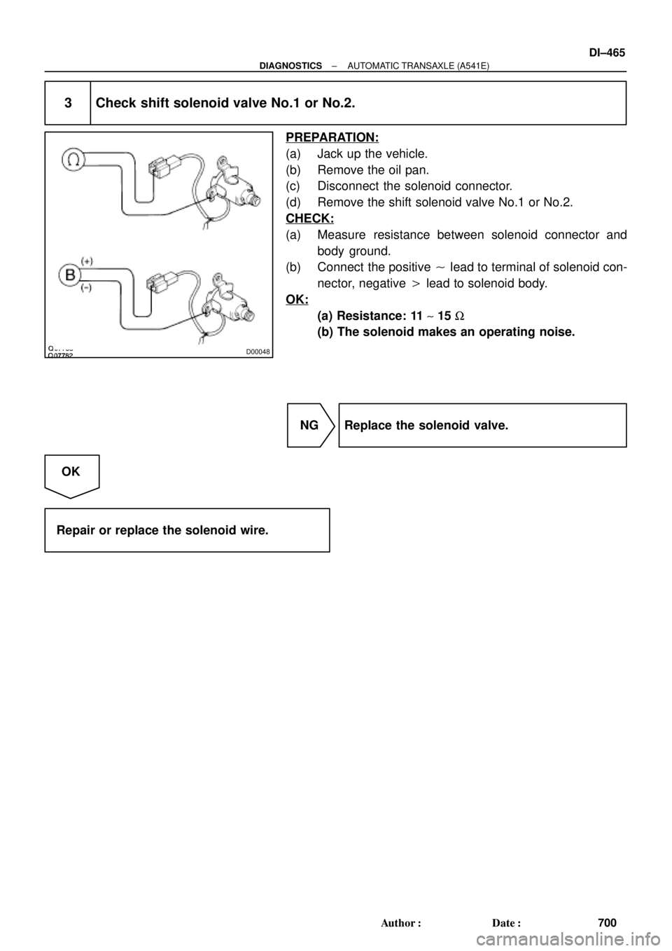
3 Check shift solenoid valve No.1 or No.2.
PREPARATION:
(a) Jack up the vehicle.
(b) Remove the oil pan.
(c) Disconnect the solenoid connector.
(d) Remove the shift solenoid valve No.1 or No.2.
CHECK:
(a) Measure resistance between solenoid connector and
body ground.
(b) Connect the positive � lead to terminal of solenoid con-
nector, negative � lead to solenoid body.
OK:
(a) Resistance: 11 ~ 15 W
(b) The solenoid makes an operating noise.
NG Replace the solenoid valve.
OK
Repair or replace the solenoid wire.
Page 2886 of 4770

701 Author�: Date�:
DTC P0770 Shift Solenoid E Malfunction
(Shift Solenoid V")
Q04874
Controlled
Pressure Line
Pressure
Drain Controlled
Pressure
Q08040
DI±466
± DIAGNOSTICSAUTOMATIC TRANSAXLE (A541E)
701 Author�: Date�:
DTC P0770 Shift Solenoid E Malfunction
(Shift Solenoid Valve SL)
SYSTEM DESCRIPTION
The ECM uses the signals from the throttle position sensor, air±
flow meter and crankshaft position sensor to monitor the en-
gagement condition of the lock±up clutch.
Then the ECM compares the engagement condition of the
lock±up clutch with the lock±up schedule in the ECM memory
to detect mechanical trouble of the shift solenoid valve SL,
valve body, torque converter clutch or automatic transaxle
(clutch, brake or gear etc.).
DTC No.DTC Detecting ConditionTrouble Area
P0770
�Lock±up does not occur when driving in the lock±up range
(normal driving at 80 km/h [50 mph]), or lock±up remains ON
in the lock±up OFF range.
(2 trip detection logic)
�When lock±up is ON, clutch or brake slips or gear is broken.�Shift solenoid valve SL is stuck open or closed
�Valve body blocked up or stuck
�Lock±up clutch
�Automatic transaxle (clutch, brake or gear etc.)
INSPECTION PROCEDURE
1 Check solenoid valve SL operation.
PREPARATION:
(a) Remove the oil pan.
(b) Remove the shift solenoid valve SL.
CHECK:
(a) Applying 490 kPa (5 kgf/cm2, 71 psi) of compressed air,
check that the solenoid valve does not leak air.
(b) When battery positive voltage is supplied to the shift sole-
noid valve, check that the solenoid valve opens.
NG Replace the solenoid valve SL.
OK
DI02M±02
Page 2891 of 4770
D00049
± DIAGNOSTICSAUTOMATIC TRANSAXLE (A541E)
DI±471
706 Author�: Date�:
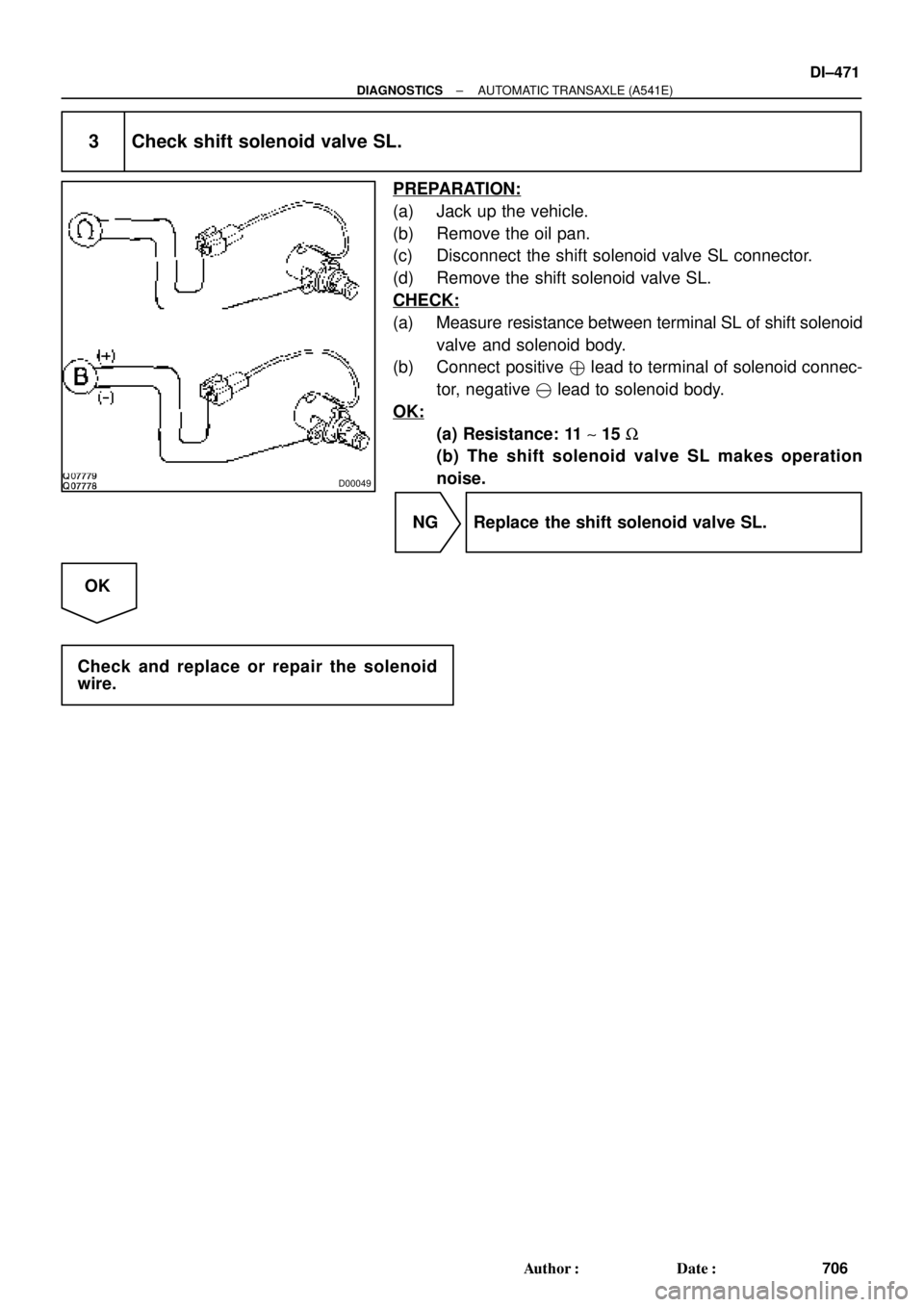
3 Check shift solenoid valve SL.
PREPARATION:
(a) Jack up the vehicle.
(b) Remove the oil pan.
(c) Disconnect the shift solenoid valve SL connector.
(d) Remove the shift solenoid valve SL.
CHECK:
(a) Measure resistance between terminal SL of shift solenoid
valve and solenoid body.
(b) Connect positive � lead to terminal of solenoid connec-
tor, negative � lead to solenoid body.
OK:
(a) Resistance: 11 ~ 15 W
(b) The shift solenoid valve SL makes operation
noise.
NG Replace the shift solenoid valve SL.
OK
Check and replace or repair the solenoid
wire.
Page 2924 of 4770
 (±)
Engine Room
R/B No. 3
3
45 6 12 (+) (±)
Engine Room
R/B No. 3
3
45 6 12 (+) (±)
Engine Room
R/B No. 3
3
45 612 (+) (±)
Engine Room
R/B No. 3
3
45 6
F07153
3
4
ABS
Actuator
AB")
F00048
12 (+) (±)
Engine Room
R/B No. 3
3
45 6 12 (+) (±)
Engine Room
R/B No. 3
3
45 6 12 (+) (±)
Engine Room
R/B No. 3
3
45 612 (+) (±)
Engine Room
R/B No. 3
3
45 6
F07153
3
4
ABS
Actuator
ABS
Solenoid
Relay
A4
A18
ECUA5
1234
56781
5 2
6 3
7 4
8
SFRH
SFRR
SRLR
SRLH
SFLH
SFLR
SRRH
SRRR
DI±504
± DIAGNOSTICSANTI±LOCK BRAKE SYSTEM (DENSO Made)
739 Author�: Date�:
INSPECTION PROCEDURE
1 Check voltage between terminals 1 and 2 of Engine Room R/B No. 3 (for ABS so-
lenoid relay).
PREPARATION:
Remove ABS solenoid relay from Engine Room R/B No. 3.
CHECK:
Measure the voltage between terminals 1 and 2 of Engine
Room R/B No. 3 (for ABS solenoid relay).
OK:
Voltage: 10 ± 14 V
NG Check and repair harness or connector.
OK
2 Check continuity between terminal 3 of ABS solenoid relay and terminal SRLR,
SRLH, SRRR, SRRH, SFLR, SFLH, SFRR or SFRH of ABS ECU.
CHECK:
Check continuity between terminal 3 of Engine Room R/B No.3
(for ABS solenoid relay) and terminal SRLR, SRLH, SRRR,
SRRH, SFLR, SRLH, SFRR or SFRH of ABS ECU.
OK:
Continuity
HINT:
Resistance of each solenoid coil
SRLR, SRRR, SFLR, SFRR: 4.3 W
SRLH, SRRH, SFLH, SFRH: 8.8 W
NG Repair or replace harness or ABS actuator.
OK
Page 2933 of 4770
W00714
A4
A5
1 2 3
4
5
6
7 8
4
A4
A5
1 2 3
4
5
6
7 8
4
A4
A5
1 2 3
4
5
6
7 8
4
A4
A5
1 2 3
4
5
6
7 8
4
A4
A5
1 2 3
4
5
6
7 8
4
A4
A5
1 2 3
4
5
6
7 8
4
± DIAGNOSTICSANTI±LOCK BRAKE SYSTEM (DENSO Made)
DI±513
748 Author�: Date�:
INSPECTION PROCEDURE
1 Check ABS actuator solenoid.
PREPARATION:
Disconnect the 2 connectors from ABS actuator.
CHECK:
Check continuity between terminals A4 ± 4 and A5 ± 1, 2, 3, 4,
5, 6, 7, 8 of ABS actuator connector.
OK:
Continuity
HINT:
Resistance of each solenoid coil is 1.2 W.
NG Replace ABS actuator.
OK
2 Check for open and short circuit in harness and connector between ABS ECU
and actuator (See page IN±31).
NG Repair or replace harness or connector.
OK
If the same code is still output after the DTC is deleted, check the contact condition of each con-
nection.
If the connections are normal, the ECU may be defective.
Page 2934 of 4770

749 Author�: Date�:
DTC31, 32, 33, 34Speed Sensor Circu")
BR3583
BR3582F00010
RotorSpeed Sensor
Magnet
To ECU
+V
±VHigh Speed
Low Speed
CoilNS
DI±514
± DIAGNOSTICSANTI±LOCK BRAKE SYSTEM (DENSO Made)
749 Author�: Date�:
DTC31, 32, 33, 34Speed Sensor Circuit
CIRCUIT DESCRIPTION
The speed sensor detects wheel speed and sends the ap-
propriate signals to the ECU. These signals are used to control
the ABS system. The front and rear rotors each have 48 serra-
tions.
When the rotors rotate, the magnetic field emitted by the perma-
nent magnet in the speed sensor generates an AC voltage.
Since the frequency of this AC voltage changes in direct propor-
tion to the speed of the rotor, the frequency is used by the ECU
to detect the speed of each wheel.
DTC No.DTC Detecting ConditionTrouble Area
31, 32, 33, 34
Detection of any of conditions from 1. through 4.:
1. Vehicle speed is at 10 km/h (6 mph) or more and the
speed sensor signal circuit is open or short circuit con-
tinues for 15 sec. or more.
2. Momentary interruption of the speed sensor signal oc-
curs 7 times or more.
3. Vehicle speed is at 20 km/h (12mph) or more and inter-
ference on the speed sensor signal continues for 5 sec.
or more.
4. Open circuit condition of the speed sensor signal circuit
continues for 0.5 sec. or more.
�Right front, left front, right rear, left rear speed sensor
�Each speed sensor circuit
�Speed sensor rotor
HINT:
�DTC No. 31 is for the right front speed sensor.
�DTC No. 32 is for the left front speed sensor.
�DTC No. 33 is for the right rear speed sensor.
�DTC No. 34 is for the left rear speed sensor.
Fail safe function:
If trouble occurs in the speed sensor circuit, the ECU cuts off current to the ABS solenoid relay and prohibits
ABS control.
DI1JM±02
Page 2972 of 4770

787 Author�: Date�:
DTC31, 32, 33, 34, 35, 36, 38, 39Sp")
BR3583
BR3582F00010
RotorSpeed Sensor
Magnet
To ECU
+V
±VHigh Speed
Low Speed
CoilNS
DI±552
± DIAGNOSTICSANTI±LOCK BRAKE SYSTEM (BOSCH Made)
787 Author�: Date�:
DTC31, 32, 33, 34, 35, 36, 38, 39Speed Sensor Circuit
CIRCUIT DESCRIPTION
The speed sensor detects wheel speed and sends the ap-
propriate signals to the ECU. These signals are used to control
the ABS system. The front and rear rotors each have 48 serra-
tions.
When the rotors rotate, the magnetic field emitted by the perma-
nent magnet in the speed sensor generates an AC voltage.
Since the frequency of this AC voltage changes in direct propor-
tion to the speed of the rotor, the frequency is used by the ECU
to detect the speed of each wheel.
DTC No.DTC Detecting ConditionTrouble Area
31, 32, 33, 34
Detection of any of conditions from 1. through 3.:
1. Vehicle speed is more than 40 km/h (25 mph), pulses
are not input for 0.01 sec.
2. After the initial start or restart and when the vehicle
speed has reached 12 km/h (7 mph), the wheel with 0
km/h (0 mph) of wheel speed is detected.
3. After the initial start or restart and when the vehicle
speed has reached 70 km/h (44 mph), front wheel with 0
km/h (0 mph) of wheel speed is detected.
�Right front, left front, right rear, left rear speed sensor
�Each speed sensor circuit
�Sensor installation
�ECU
35, 36, 38, 39Detecting abnormality in the resistance value of each speed
sensor.�Right front, left front, right rear, left rear speed sensor
�Each speed sensor circuit
�ECU
HINT:
�DTC No. 31 and 35 are for the right front speed sensor.
�DTC No. 32 and 36 are for the left front speed sensor.
�DTC No. 33 and 38 are for the right rear speed sensor.
�DTC No. 34 and 39 are for the left rear speed sensor.
Fail safe function:
If trouble occurs in the speed sensor circuit, the ECU cuts off current to the ABS solenoid valve relay and
prohibits ABS control.
DI043±04