Page 3416 of 4770
 EM±24
± ENGINE MECHANICAL (5S±FE)TIMING BELT
1196 Author�: Date�:
5. TEMPORARILY INSTALL TIMING BELT
NOTICE:
The engine should be cold.
(a) Us")
S05574
S05944
S05578
P25230Length = 660 mm (25.98 in.) EM±24
± ENGINE MECHANICAL (5S±FE)TIMING BELT
1196 Author�: Date�:
5. TEMPORARILY INSTALL TIMING BELT
NOTICE:
The engine should be cold.
(a) Using the crankshaft pulley bolt, turn the crankshaft and
align the timing marks of the crankshaft timing pulley and
oil pump body.
(b) Remove any oil or water on the crankshaft pulley, oil
pump pulley, water pump pulley, No.1 idler pulley and
No.2 idler pulley, and keep them clean.
(c) Install the timing belt on the crankshaft timing pulley, oil
pump pulley, No.1 idler pulley, water pump pulley and
No.2 idler pulley.
HINT:
When re±using timing belt:
Align the points marked during removal, and install the belt with
the arrow pointing in the direction of engine revolution.
6. INSTALL TIMING BELT GUIDE
Install the guide, facing the cup side outward.
7. INSTALL NO.1 TIMING BELT COVER
(a) Check that the timing belt cover gasket has no cracks or
peeling, etc.
If the gasket has cracks or peeling, etc., replace it using these
steps:
(1) Using a screwdriver and gasket scraper, remove all
the old gasket material.
(2) Thoroughly clean all components to remove all the
loose material.
(3) Remove the backing paper from a new gasket and
install the gasket evenly to the part of the timing belt
cover shaded black in the illustration.
(4) After installing the gasket, press down on it so that
the adhesive firmly sticks to the timing belt cover.
Page 3418 of 4770
S05594
SST
A02592
S05582
S05931
S05581
Loosen EM±26
± ENGINE MECHANICAL (5S±FE)TIMING BELT
1198 Author�: Date�:
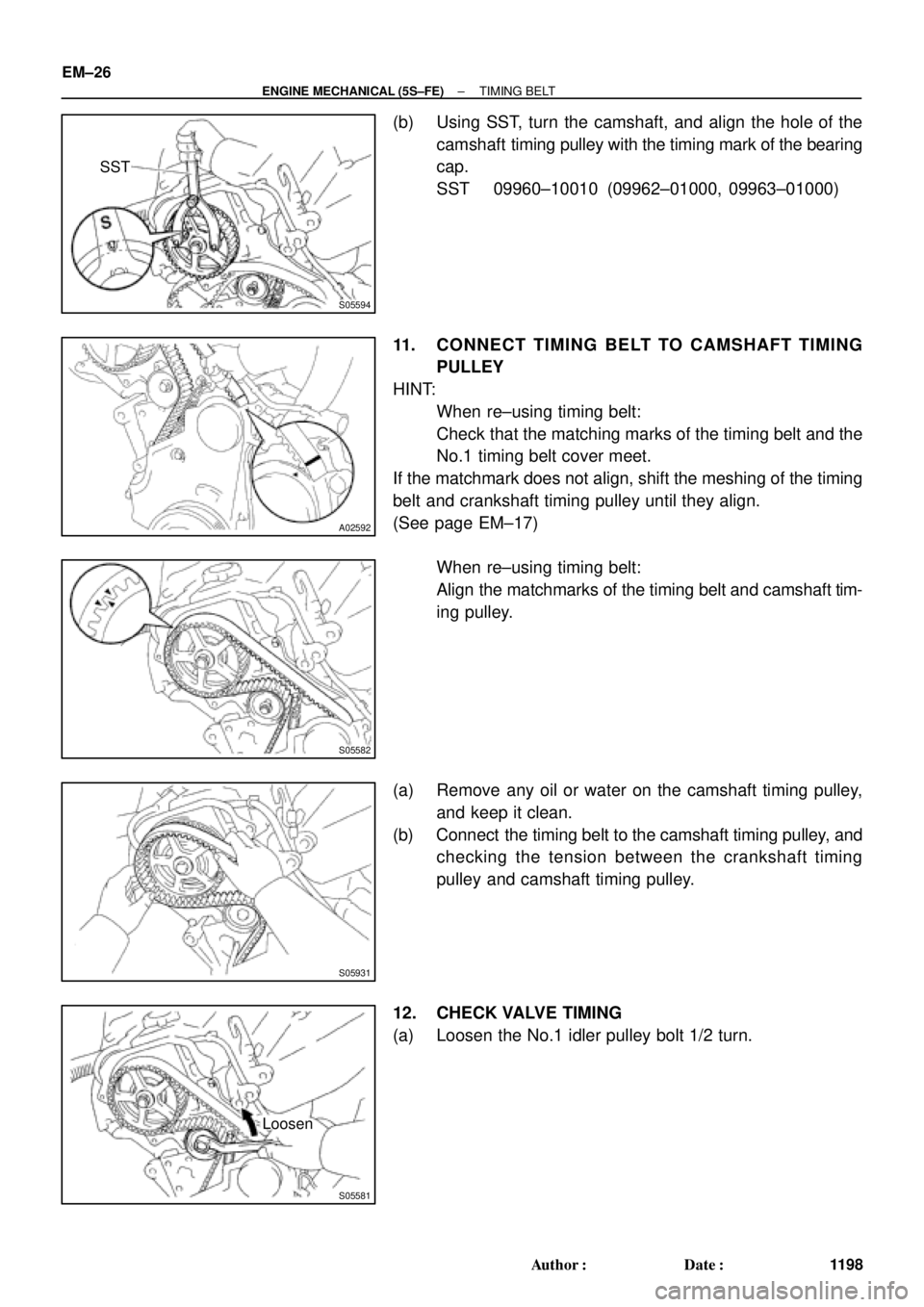
(b) Using SST, turn the camshaft, and align the hole of the
camshaft timing pulley with the timing mark of the bearing
cap.
SST 09960±10010 (09962±01000, 09963±01000)
11. CONNECT TIMING BELT TO CAMSHAFT TIMING
PULLEY
HINT:
�When re±using timing belt:
Check that the matching marks of the timing belt and the
No.1 timing belt cover meet.
If the matchmark does not align, shift the meshing of the timing
belt and crankshaft timing pulley until they align.
(See page EM±17)
�When re±using timing belt:
Align the matchmarks of the timing belt and camshaft tim-
ing pulley.
(a) Remove any oil or water on the camshaft timing pulley,
and keep it clean.
(b) Connect the timing belt to the camshaft timing pulley, and
checking the tension between the crankshaft timing
pulley and camshaft timing pulley.
12. CHECK VALVE TIMING
(a) Loosen the No.1 idler pulley bolt 1/2 turn.
Page 3422 of 4770

A01562
Generator Wire
Generator
Connector
GeneratorWire Clamp
Wire
Clamp
ECT Sender
Gauge ConnectorThrottle BodyThrottle Position
Sensor ConnectorIgnition Coil Connector
IAC Valve
Connector
Heater Water Hose
Radiator Hose ECT Sensor
Connector
Water Outlet
Noise Filter Connector
Oil Pressure Switch Connector
Ignition Coil and No.2 Intake
Manifold Assembly
(with High±Tension Cord)
A/F Sensor Connector (California) or
Heated Oxygen Sensor (Bank 1 Sensor 1)
Connector (Except California)
(TMMK Made) � Gasket� Gasket � Gasket
(TMC Made)No.1 Exhaust
Manifold Stay
No.2 Exhaust
Manifold Stay No.1 Exhaust
Manifold Heat
Insulator
Exhaust Manifold,
No.2 and No.3
Exhaust Manifold
Heat Insulator
Assembly
� Non±reusable partExcept California
19 (195, 14)
49 (500, 36)
49 (500, 36)
: Specified torqueN´m (kgf´cm, ft´lbf)x 6
Exhaust Manifold,
No.2 and no.3
Exhaust Manifold
Heat Insulator
Assenbly
(California)
No.1 Exhaust
Manifold Heat
Insulator (California) (TMMK Made)
(TMC Made)
EM±30
± ENGINE MECHANICAL (5S±FE)CYLINDER HEAD
1202 Author�: Date�:
Page 3424 of 4770

A07368
Spark Plug
Grommet
Cylinder Head Cover
Gasket
Camshaft Bearing Cap
� Camshaft Oil Seal
Camshaft Timing Pulley
Snap Ring
Wave Washer
Camshaft Position Sensor Connector
Camshaft Position Sensor Assembly
Wire Clamp
No. 3 Timing Belt Cover
No.2 Timing Belt Cover� Oil Seal
Valve Guide
Bushing
Cylinder
Head
Gasket Adjusting Shim
Valve Lifter
Keeper
Spring Retainer
Valve Spring
Spring Seat
Valve
LH Engine
Hanger
Semi±Circular
Plug
Oil Pressure
Switch
Camshaft Gear Spring
Camshaft Sub±Gear
Semi±Circular
Plug
Tension Spring
No.1 Idler Pulley
*
1
GasketTiming Belt
Cylinder Head Intake
CamshaftExhaust
Camshaft
Wire
Clamp
Wire
Clamp
Generator Bracket and
RH Engine Hanger
Assembly
N´m (kgf´cm, ft´lbf)
*
2 For use with SST
� Non±reusable part
18 (180, 13)
44 (450, 33)
19 (190, 14)
*
237 (380, 27)1st 49 (500, 36)
2nd Turn 90°
42 (425, 31)
x 10�
�
: Specified torque
See page EM±53
*1
Replace only if damaged
54 (550, 40)
EM±32
± ENGINE MECHANICAL (5S±FE)CYLINDER HEAD
1204 Author�: Date�:
Page 3426 of 4770
(d)
(e)
A07364
ConnectorClamp
EM±34
± ENGINE MECHANICAL (5S±FE)CYLINDER HEAD
1206 Author�: Date�:
(j) California:
Disconnect the A/F sensor connector for the wiring side")
S05548
Wire
Clamp
A01564(c)(d)
(e)
A07364
ConnectorClamp
EM±34
± ENGINE MECHANICAL (5S±FE)CYLINDER HEAD
1206 Author�: Date�:
(j) California:
Disconnect the A/F sensor connector for the wiring side
from the bracket on the LH engine hanger.
(k) Except California:
Disconnect the heated oxygen sensor (bank 1 sensor 1)
connector for the wiring side from the bracket on the LH
engine hanger.
5. REMOVE THROTTLE BODY (See page SF±32)
6. REMOVE IGNITION COILS, NO.2 INTAKE MANIFOLD
STAY AND HIGH±TENSION CORDS ASSEMBLY
(a) Disconnect the 2 ignition coil connectors.
(b) Disconnect the 4 high±tension cords from the 2 clamps
on the cylinder head cover.
(c) Disconnect the 4 high±tension cords from the spark
plugs.
(d) Disconnect the wire clamp from the manifold stay.
(e) TMC Made:
Remove the 2 nuts, 2 bolts, 2 ignition coils, manifold stay
and 4 high±tension cords assembly.
(f) TMMK Made:
Remove the nut, 3 bolts, 2 ignition coils, manifold stay and
4 high±tension cords assembly.
7. DISCONNECT OIL PRESSURE SWITCH CONNECTOR
8. DISCONNECT NOISE FILTER CONNECTOR
9. REMOVE WATER OUTLET
(a) Disconnect the ECT sensor connector.
(b) Disconnect the ECT sender gauge connector.
(c) Disconnect the radiator hose from the water outlet.
(d) Disconnect the water bypass pipe hose from the water
outlet.
(e) Disconnect the heater water hose from the water outlet.
(f) Remove the 2 nuts, water outlet and gasket.
10. REMOVE INTAKE MANIFOLD STAY
Remove the bolt, nut and intake manifold stay.
11. REMOVE EGR VALVE AND VACUUM MODULATOR
(a) Disconnect the VSV connector for the EGR.
(b) Disconnect the hose clamp from the bracket on the intake
manifold.
(c) Remove the bolt, and disconnect the VSV for EGR from
the intake manifold.
Page 3429 of 4770
CYLINDER HEAD
EM±37
1209 Author�: Date�:
NOTICE:
�Support the timing belt, so the meshing of the crank-
shaft timing pulley and")
A02593
S05933
P03355
10 ± 45°
Knock
Pin
± ENGINE MECHANICAL (5S±FE)CYLINDER HEAD
EM±37
1209 Author�: Date�:
NOTICE:
�Support the timing belt, so the meshing of the crank-
shaft timing pulley and timing belt does not shift.
�Be careful not to drop anything inside the timing belt
cover.
�Do not allow the belt to come into contact with oil, wa-
ter or dust.
21. REMOVE ENGINE HANGERS AND GENERATOR
BRACKET
(a) Remove the 3 bolts, the generator bracket and RH engine
hanger assembly.
(b) Remove the bolt and LH engine hanger.
22. REMOVE OIL PRESSURE SWITCH
23. REMOVE CYLINDER HEAD COVER
Remove the 4 nuts, grommets, head cover and gasket.
HINT:
Arrange the grommets in the correct order, so that they can be
reinstalled into their original positions. This minimizes any pos-
sibility of oil leakage due to reuse of the grommets in different
positions.
24. REMOVE CAMSHAFTS
NOTICE:
Since the thrust clearance of the camshaft is small, the
camshaft must be kept level while it is being removed. If the
camshaft is not kept level, the portion of the cylinder head
receiving the shaft thrust may crack or be damaged, caus-
ing the camshaft to seize or break. To avoid this, the follow-
ing steps should be carried out.
(a) Remove the exhaust camshaft.
(1) Set the knock pin of the intake camshaft at 10 ± 45°
BTDC of camshaft angle.
HINT:
The above angle allows No.2 and No.4 cylinder cam lobes of
the exhaust camshaft to push their valve lifters evenly.
Page 3431 of 4770
CYLINDER HEAD
EM±39
1211 Author�: Date�:
(b) Remove the intake camshaft.
(1) Set the knock pin of the intak")
P03358
8 0 ± 11 5°
Knock
Pin
P03359
P03360
1 2
3 45 6
P03361
± ENGINE MECHANICAL (5S±FE)CYLINDER HEAD
EM±39
1211 Author�: Date�:
(b) Remove the intake camshaft.
(1) Set the knock pin of the intake camshaft at 80 ±
11 5° BTDC of camshaft angle.
HINT:
The above angle allows the No.1 and No.3 cylinder cam lobes
of intake camshaft to push their valve lifters evenly.
(2) Remove the 2 bolts, front bearing cap and oil seal.
(3) Uniformly loosen and remove the 6 bolts on the
No.1, No.3 and No.4 bearing caps in several
passes, in the sequence shown.
NOTICE:
Do not remove the No.2 bearing cap bolts at this stage.
(4) Remove the No.1, No.3 and No.4 bearing caps.
(5) Alternately loosen and remove the 2 bolts on the
No.2 bearing cap.
HINT:
�As the 2 No.2 bearing cap bolts are loosened, make sure
that the camshaft is lifted out straight and level, after
breaking adhesion on the front bearing cap.
�If the camshaft is not being lifted out straight and level, re-
tighten the 2 No.2 bearing cap bolts. Reverse the order
of above steps from (5) to (1) and reset the knock pin of
the intake camshaft at 80 ± 115° BTDC, and repeat steps
from (2) to (5) once again.
NOTICE:
Do not pry on or attempt to force the camshaft with a tool
or other object.
(6) Remove the No.2 bearing cap and camshaft.
Page 3433 of 4770
EM089±03
P03265
SST
P03266
± ENGINE MECHANICAL (5S±FE)CYLINDER HEAD
EM±41
1213 Author�: Date�:
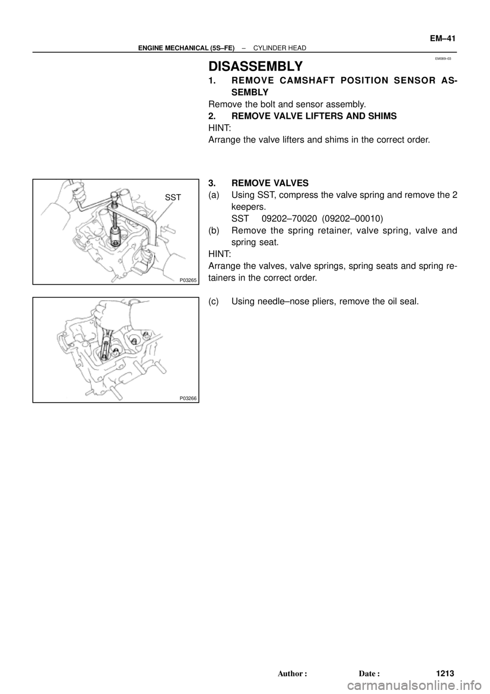
DISASSEMBLY
1. REMOVE CAMSHAFT POSITION SENSOR AS-
SEMBLY
Remove the bolt and sensor assembly.
2. REMOVE VALVE LIFTERS AND SHIMS
HINT:
Arrange the valve lifters and shims in the correct order.
3. REMOVE VALVES
(a) Using SST, compress the valve spring and remove the 2
keepers.
SST 09202±70020 (09202±00010)
(b) Remove the spring retainer, valve spring, valve and
spring seat.
HINT:
Arrange the valves, valve springs, spring seats and spring re-
tainers in the correct order.
(c) Using needle±nose pliers, remove the oil seal.