Page 3477 of 4770
A07353
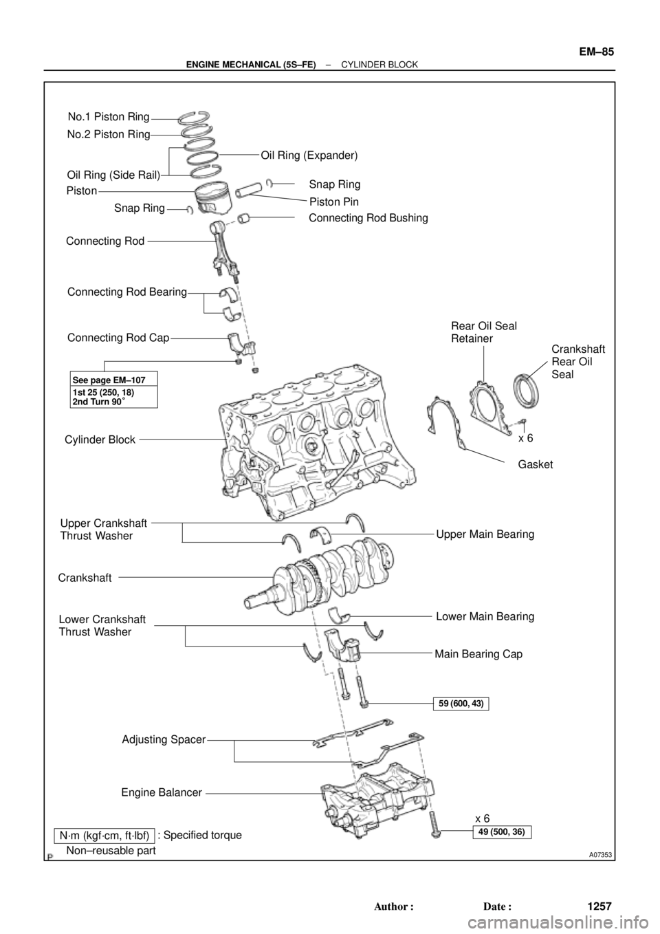
No.1 Piston Ring
No.2 Piston Ring
Oil Ring (Side Rail)
� Snap Ring
Connecting Rod
Connecting Rod Bearing
Connecting Rod Cap
Cylinder Block
Upper Crankshaft
Thrust Washer
Crankshaft
Lower Crankshaft
Thrust Washer
Adjusting Spacer
Engine Balancerx 6
Main Bearing CapLower Main Bearing Upper Main Bearing� Gasket Rear Oil Seal
Retainer
Crankshaft
Rear Oil
Seal � Connecting Rod BushingPiston Pin � Snap Ring Oil Ring (Expander)
� Non±reusable part
N´m (kgf´cm, ft´lbf)x 6 Piston
1st 25 (250, 18)
2nd Turn 90°
59 (600, 43)
49 (500, 36): Specified torque
See page EM±107
�
± ENGINE MECHANICAL (5S±FE)CYLINDER BLOCK
EM±85
1257 Author�: Date�:
Page 3478 of 4770
CYLINDER BLOCK
1258 Author�: Date�:
DISASSEMBLY
1. INSTALL ENGINE TO ENGINE STAND FOR DIS-
ASSEMBLY
2. REMOVE TIMING BELT AND PULLEYS
(See pa")
EM0YW±01
S06011
1
3
2 EM±86
± ENGINE MECHANICAL (5S±FE)CYLINDER BLOCK
1258 Author�: Date�:
DISASSEMBLY
1. INSTALL ENGINE TO ENGINE STAND FOR DIS-
ASSEMBLY
2. REMOVE TIMING BELT AND PULLEYS
(See page EM±17)
3. REMOVE CYLINDER HEAD ASSEMBLY
(a) Remove the 3 bolts and No.3 timing belt cover.
(b) Remove the cylinder head cover.
(1) Disconnect the PCV hose from the intake manifold.
(2) Remove the 4 nuts, 4 grommets, head cover and
gasket.
(c) Remove the camshafts. (See page EM±33)
(d) Disconnect the knock sensor 1 connector.
(e) Disconnect the crankshaft position sensor connector.
(f) Disconnect the wire clamp from the generator drive belt
adjusting bar.
(g) Disconnect the IAC valve water bypass hose from the wa-
ter bypass pipe.
(h) Disconnect the water bypass hose (from the water by-
pass pipe) from the water outlet.
(i) Remove the bolt holding the VSV for EGR to the intake
manifold.
(j) Remove the 2 bolts holding the water bypass pipe to the
cylinder head.
(k) Remove the cylinder head assembly.
(See page EM±33)
4. REMOVE OIL DIPSTICK
5. REMOVE OIL PAN AND OIL PUMP
(a) Disconnect the crankshaft position sensor connector
from the generator drive belt adjusting bar.
(b) Remove the oil pan and oil pump. (See page LU±7)
6. REMOVE PS PUMP BRACKET
Remove the 3 bolts and pump bracket.
7. REMOVE KNOCK SENSOR 1 (See page SF±57)
8. REMOVE OIL FILTER (See page LU±2)
9. REMOVE WATER PUMP, WATER BYPASS PIPE AND
OIL COOLER (w/ OIL COOLER) ASSEMBLY
(a) w/ Oil Cooler:
Remove the nut and union bolt, and disconnect the oil
cooler. Remove the O±ring.
(b) Remove the bolt and generator drive belt adjusting bar.
(c) Remove the 3 bolts in the sequence shown, remove the
water pump, water bypass pipe, oil cooler (w/ oil cooler)
assembly and O±ring.
Page 3479 of 4770
CYLINDER BLOCK
EM±87
1")
P05527
P00717
Z19418
No.1 Balance
CrankshaftA
A B B
1 23
4
30°TDC
Shaft Gear
Gear
210°
280°
100°
P01477
Z19410
No.1 Balance Shaft
Mark A
Mark B
± ENGINE MECHANICAL (5S±FE)CYLINDER BLOCK
EM±87
1259 Author�: Date�:
10. REMOVE REAR OIL SEAL RETAINER
Remove the 6 bolts, retainer and gasket.
11. CHECK THRUST CLEARANCES OF NO.1 AND NO.2
BALANCE SHAFTS OF ENGINE BALANCER
Using a dial indicator, measure the thrust clearance while mov-
ing the balance shaft back and forth.
Standard thrust clearance:
0.060 ± 0.110 mm (0.0024 ± 0.0043 in.)
Maximum clearance: 0.11 mm (0.0043 in.)
If the clearance is greater than maximum, replace the balance
shaft housings and bearings. If necessary, replace the balance
shafts.
12. CHECK AND ADJUST BACKLASH OF CRANKSHAFT
GEAR AND NO.1 BALANCE SHAFT GEAR
NOTICE:
Backlash between the crankshaft gear and No.1 balance
shaft gear varies with the rotation of the balance shaft and
the deviation of the crankshaft gear. Accordingly, it is nec-
essary to measure the backlash at the 4 points shown in
the illustration on the left.
(a) Turn the crankshaft 2 or 3 times to settle the crankshaft
gear and No.1 balance shaft gear.
(b) When the No.1 piston is at TDC, check that the punch
marks shown in the illustration of the balance shafts are
aligned with the grooves of the No.2 housing.
(c) Check that punch marks A and B are at the positions on
the No.1 balance shaft indicated in the illustration.
Page 3483 of 4770
CYLINDER BLOCK
EM±91
1263 Author�: Date�:
13. REMOVE ENGINE BALANCER
(a) Uniformly loosen and remove the 6 bolts in several")
S03789
1
4
6
5
2
3
N00991
P03166
N00924
N00993
± ENGINE MECHANICAL (5S±FE)CYLINDER BLOCK
EM±91
1263 Author�: Date�:
13. REMOVE ENGINE BALANCER
(a) Uniformly loosen and remove the 6 bolts in several
passes, in the sequence shown.
(b) Remove the engine balancer and spacers.
14. CHECK CONNECTING ROD THRUST CLEARANCE
Using a dial indicator, measure the thrust clearance while mov-
ing the connecting rod back and forth.
Standard thrust clearance:
0.160 ± 0.312 mm (0.0063 ± 0.0123 in.)
Maximum thrust clearance: 0.35 mm (0.0138 in.)
If the thrust clearance is greater than maximum, replace the
connecting rod assembly. If necessary, replace the crankshaft.
15. REMOVE CONNECTING ROD CAPS AND CHECK OIL
CLEARANCE
(a) Check the matchmarks on the connecting rod and cap to
ensure correct reassembly.
(b) Remove the 2 connecting rod cap nuts.
(c) Using a plastic±faced hammer, lightly tap the connecting
rod bolts and lift off the connecting rod cap.
HINT:
Keep the lower bearing inserted with the connecting rod cap.
(d) Cover the connecting rod bolts with a short piece of hose
to protect the crankshaft from damage.
(e) Clean the crank pin and bearing.
(f) Check the crank pin and bearing for pitting and scratches.
If the crank pin or bearing is damaged, replace the bearings. If
necessary, grind or replace the crankshaft.
Page 3484 of 4770
CYLINDER BLOCK
1264 Author�: Date�:
(g) Lay a strip of Plastigage across the crank pin.
(h) Inst")
N00999
Plastigage
Z19381
N00920
N00932
Mark
1, 2 or 3Mark
1, 2 or 3 EM±92
± ENGINE MECHANICAL (5S±FE)CYLINDER BLOCK
1264 Author�: Date�:
(g) Lay a strip of Plastigage across the crank pin.
(h) Install the connecting rod cap.(See page EM±107)
NOTICE:
Do not turn the crankshaft.
(i) Remove the connecting rod cap.
(See steps (b) and (c))
(j) Measure the Plastigage at its widest point.
Standard oil clearance:
STD0.024 ± 0.055 mm (0.0009 ± 0.0022 in.)
U/S 0.250.023 ± 0.069 mm (0.0009 ± 0.0027 in.)
Maximum oil clearance: 0.08 mm (0.0031 in.)
If the oil clearance is greater than maximum, replace the bear-
ings. If necessary, grind or replace the crankshaft.
HINT:
If using a standard bearing, replace it with one having the same
number marked on the connecting rod cap. There are 3 sizes
of standard bearings, marked º1º, º2º and º3º accordingly.
Reference
Standard sized bearing center wall thickness:
Mark º1º1.484 ± 1.488 mm (0.0584 ± 0.0586 in.)
Mark º2º1.488 ± 1.492 mm (0.0586 ± 0.0587 in.)
Mark º3º1.492 ± 1.496 mm (0.0587 ± 0.0589 in.)
(k) Completely remove the Plastigage.
Page 3485 of 4770
CYLINDER BLOCK
EM±93
1265 Author�: Date�:
16. REMOVE PISTON AND CONNECTING ROD AS-
SEMBLIES
(a) Using a ridge reamer,")
S05989
N00993
P00598
P00105
481062
1
5
9
7
3
S06014
± ENGINE MECHANICAL (5S±FE)CYLINDER BLOCK
EM±93
1265 Author�: Date�:
16. REMOVE PISTON AND CONNECTING ROD AS-
SEMBLIES
(a) Using a ridge reamer, remove all the carbon from the top
of the cylinder.
(b) Cover the connecting rod bolts with a short piece of hose
to protect the crankshaft from damage.
(c) Push the piston, connecting rod assembly and upper
bearing through the top of the cylinder block.
HINT:
�Keep the bearings, connecting rod and cap together.
�Arrange the piston and connecting rod assemblies in the
correct order.
17. CHECK CRANKSHAFT THRUST CLEARANCE
Using a dial indicator, measure the thrust clearance while prying
the crankshaft back and forth with a screwdriver.
Standard thrust clearance:
0.020 ± 0.220 mm (0.0008 ± 0.0087 in.)
Maximum thrust clearance: 0.30 mm (0.0118 in.)
If the thrust clearance is greater than maximum, replace the
thrust washer as a set.
Thrust washer thickness:
2.440 ± 2.490 mm (0.0961 ± 0.0980 in.)
18. REMOVE MAIN BEARING CAPS AND CHECK OIL
CLEARANCE
(a) Uniformly loosen and remove the 10 main bearing cap
bolts in several passes, in the sequence shown.
(b) Using 2 screwdrivers, pry out the main bearing cap, and
remove the 5 main bearing caps, 5 lower bearings and 2
lower thrust washers (No.3 main bearing cap only).
HINT:
�Keep the lower bearing and main bearing cap together.
�Arrange the main bearing caps and lower thrust washers
in the correct order.
(c) Lift out the crankshaft.
Page 3486 of 4770
CYLINDER BLOCK
1266 Author�: Date�:
HINT:
Keep the upper bearing and upper thrust washers together with
the cylind")
N01000
Plastigage
P00104
10 159
73
4
86
2
N00988
EM±94
± ENGINE MECHANICAL (5S±FE)CYLINDER BLOCK
1266 Author�: Date�:
HINT:
Keep the upper bearing and upper thrust washers together with
the cylinder block.
(d) Clean each main journal and bearing.
(e) Check each main journal and bearing for pitting and
scratches.
If the journal or bearing is damaged, replace the bearings. If
necessary, grind or replace the crankshaft.
(f) Place the crankshaft on the cylinder block.
(g) Lay a strip of Plastigage across each journal.
(h) Install the main bearing caps. (See page EM±107)
NOTICE:
Do not turn the crankshaft.
(i) Remove the main bearing caps.
(See steps (a) and (b))
(j) Measure the Plastigage at its widest point.
Standard clearance:
No.3 STD
U/S 0.250.025 ± 0.044 mm (0.0010 ± 0.0017 in.)
0.027 ± 0.067 mm (0.0011 ± 0.0026 in.)
Others STD
U/S 0.250.015 ± 0.034 mm (0.0006 ± 0.0013 in.)
0.019 ± 0.059 mm (0.0007 ± 0.0023 in.)
Maximum clearance: 0.08 mm (0.0031 in.)
HINT:
If replacing the cylinder block subassembly, the bearing stan-
dard clearance will be:
No.30.027 ± 0.054 mm (0.0001 ± 0.0021 in.)
Others0.017 ± 0.044 mm (0.0007 ± 0.0017 in.)
If the oil clearance is greater than maximum, replace the bear-
ings. If necessary, grind or replace the crankshaft.
Page 3488 of 4770
A06590
A06589
A06587
A01774
A01775
EM±96
± ENGINE MECHANICAL (5S±FE)CYLINDER BLOCK
1268 Author�: Date�:
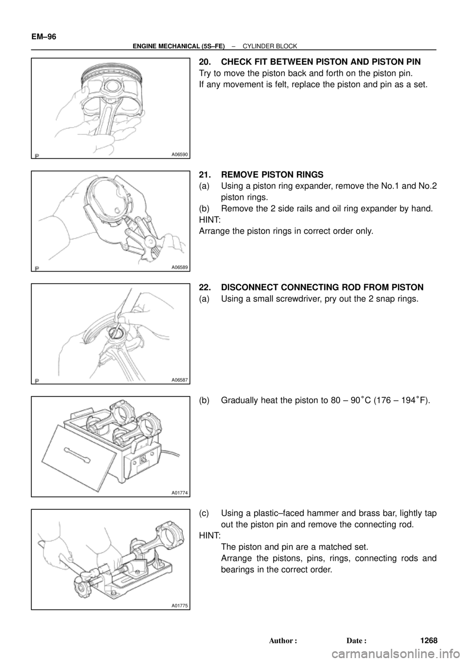
20. CHECK FIT BETWEEN PISTON AND PISTON PIN
Try to move the piston back and forth on the piston pin.
If any movement is felt, replace the piston and pin as a set.
21. REMOVE PISTON RINGS
(a) Using a piston ring expander, remove the No.1 and No.2
piston rings.
(b) Remove the 2 side rails and oil ring expander by hand.
HINT:
Arrange the piston rings in correct order only.
22. DISCONNECT CONNECTING ROD FROM PISTON
(a) Using a small screwdriver, pry out the 2 snap rings.
(b) Gradually heat the piston to 80 ± 90°C (176 ± 194°F).
(c) Using a plastic±faced hammer and brass bar, lightly tap
out the piston pin and remove the connecting rod.
HINT:
�The piston and pin are a matched set.
�Arrange the pistons, pins, rings, connecting rods and
bearings in the correct order.