Page 3499 of 4770
EM08L±03
A06586
A01776
A07349
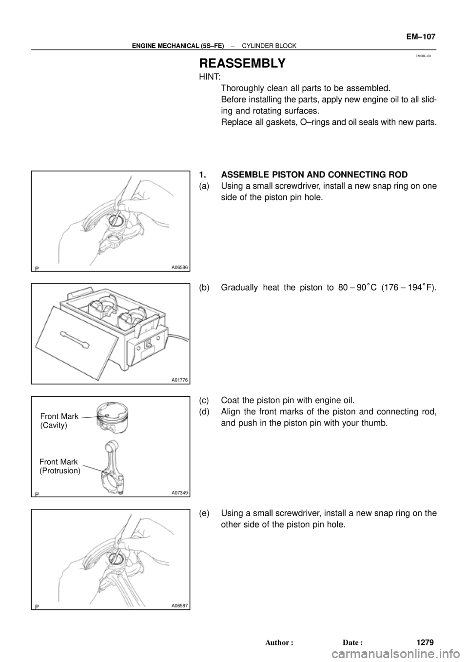
Front Mark
(Cavity)
Front Mark
(Protrusion)
A06587
± ENGINE MECHANICAL (5S±FE)CYLINDER BLOCK
EM±107
1279 Author�: Date�:
REASSEMBLY
HINT:
�Thoroughly clean all parts to be assembled.
�Before installing the parts, apply new engine oil to all slid-
ing and rotating surfaces.
�Replace all gaskets, O±rings and oil seals with new parts.
1. ASSEMBLE PISTON AND CONNECTING ROD
(a) Using a small screwdriver, install a new snap ring on one
side of the piston pin hole.
(b) Gradually heat the piston to 80 ± 90°C (176 ± 194°F).
(c) Coat the piston pin with engine oil.
(d) Align the front marks of the piston and connecting rod,
and push in the piston pin with your thumb.
(e) Using a small screwdriver, install a new snap ring on the
other side of the piston pin hole.
Page 3500 of 4770
 No.1
Compression
Ring
No.2
Compression
RingLower Side Rail
P
P00797
P05533
22.9 mm
19.2 mm Others
No.3
P05353
EM�")
A06588
No.1
No.2Code Mark
Code Mark
A07351
Upper Side Rail
ExpanderFront
Mark
(Cavity) No.1
Compression
Ring
No.2
Compression
RingLower Side Rail
P
P00797
P05533
22.9 mm
19.2 mm Others
No.3
P05353
EM±108
± ENGINE MECHANICAL (5S±FE)CYLINDER BLOCK
1280 Author�: Date�:
2. INSTALL PISTON RINGS
(a) Install the oil ring expander and 2 side rails by hand.
(b) Using a piston ring expander, install the No.2 and No.1
piston rings with the code mark facing upward.
Code mark:
No.11N or T
No.22N or 2T
(c) Position the piston rings so that the ring ends are as
shown.
NOTICE:
Do not align the ring ends.
3. INSTALL BEARINGS
(a) Align the bearing claw with the groove of the connecting
rod or connecting cap.
(b) Install the bearings in the connecting rod and connecting
rod cap.
4. INSTALL MAIN BEARINGS
HINT:
�Main bearings come in widths of 19.2 mm (0.756 in.) and
22.9 mm (0.902 in.). Install the 22.9 mm (0.902 in.) bear-
ings in the No.3 cylinder block journal position with the
main bearing cap. Install the 19.2 mm (0.756 in.) bearings
in the other positions.
�Upper bearings have an oil groove and oil holes; lower
bearings do not.
(a) Align the bearing claw with the claw groove of the cylinder
block, and push in the 5 upper bearings.
Page 3501 of 4770
CYLINDER BLOCK
EM±109
1281 Author�: Date�:
(b) Align the bearing claw with the claw groove of the")
P03177
Mark
1, 2, 3, 4, or 5
P05354
P03173
S06012
P00104
1
10
735
84269
± ENGINE MECHANICAL (5S±FE)CYLINDER BLOCK
EM±109
1281 Author�: Date�:
(b) Align the bearing claw with the claw groove of the main
bearing cap, and push in the 5 lower bearings.
HINT:
A number is marked on each main bearing cap to indicate the
installation position.
5. INSTALL UPPER THRUST WASHERS
Install the 2 thrust washers under the No.3 journal position of
the cylinder block with the oil grooves facing outward.
6. PLACE CRANKSHAFT ON CYLINDER BLOCK
7. INSTALL MAIN BEARING CAPS AND LOWER
THRUST WASHERS
(a) Install the 2 thrust washers on the No.3 bearing cap with
the grooves facing outward.
(b) Install the 5 main bearing caps in their proper locations.
HINT:
Each bearing cap has a number and front mark.
(c) Apply a light coat of engine oil on the threads and under
the heads of the main bearing cap bolts.
(d) Install and uniformly tighten the 10 bolts of the main bear-
ing cap in several passes, in the sequence shown.
Torque: 59 N´m (600 kgf´cm, 43 ft´lbf)
(e) Check that the crankshaft turns smoothly.
8. CHECK CRANKSHAFT THRUST CLEARANCE
(See page EM±86)
Page 3502 of 4770

Front
N01001
Front Mark
(Protrusion)
Z19381
EM±110
± ENGINE MECHANICAL (5S±FE)CYLINDER BLOCK
1282 Author�: Date�:
9. INSTALL PISTON AND CONNECTING ROD AS-
SEM")
EM2082
A06614
Push Front Mark
(Cavity)
Front
N01001
Front Mark
(Protrusion)
Z19381
EM±110
± ENGINE MECHANICAL (5S±FE)CYLINDER BLOCK
1282 Author�: Date�:
9. INSTALL PISTON AND CONNECTING ROD AS-
SEMBLES
(a) Cover the connecting rod bolts with a short piece of hose
to protect the crankshaft from damage.
(b) Using a piston ring compressor, push the correctly num-
bered piston and connecting rod assemblies into each
cylinder with the front mark of the piston facing forward.
10. PLACE CONNECTING ROD CAP ON CONNECTING
ROD
(a) Match the numbered connecting rod cap with the con-
necting rod.
(b) Install the connecting rod cap with the front mark facing
forward.
11. INSTALL CONNECTING ROD CAP NUTS
HINT:
�The cap nuts are tightened in 2 progressive steps (steps
(b) and (d)).
�If any one of the connecting rod bolts is broken or de-
formed, replace it.
(a) Apply a light coat of engine oil on the threads and under
the nuts of the connecting rod cap.
(b) Install and alternately tighten the 2 cap nuts in several
passes.
Torque: 25 N´m (250 kgf´cm, 18 ft´lbf)
If any one of the cap nuts does not meet the torque specifica-
tion, replace the connecting rod bolt and cap nut as a set.
Page 3504 of 4770
CYLINDER BLOCK
1284 Author�: Date�:
(g) While pulling the center part of the engine balancer in the
direction of the arrow,")
S04614
1
Pull 53
426
P01477
Z19357
13
2 EM±112
± ENGINE MECHANICAL (5S±FE)CYLINDER BLOCK
1284 Author�: Date�:
(g) While pulling the center part of the engine balancer in the
direction of the arrow, uniformly tighten the 6 bolts in sev-
eral passes, in the sequence shown.
Torque: 49 N´m (500 kgf´cm, 36 ft´lbf)
(h) Recheck that the punch marks of the balance shafts are
aligned with the grooves of the No.2 housing.
14. CHECK AND ADJUST BACKLASH OF CRANKSHAFT
GEAR AND NO.1 BALANCE SHAFT GEAR
(See page EM±86)
15. INSTALL REAR OIL SEAL RETAINER
Install a new gasket and the retainer with the 6 bolts.
Torque: 13 N´m (130 kgf´cm, 9 ft´lbf)
16. INSTALL WATER PUMP, WATER BYPASS PIPE AND
OIL COOLER (w/ OIL COOLER) ASSEMBLY
(a) Install a new O±ring to the water pump cover.
(b) Install the water pump, water bypass pipe and oil cooler
(w/ oil cooler) assembly with the 3 bolts. Tighten the bolts
in the sequence shown.
Torque: 8.8 N´m (90 kgf´cm, 78 in.´lbf)
(c) Install the generator drive belt adjusting bar with the bolt.
Torque: 22 N´m (224 kgf´cm, 16 ft´lbf)
(d) w/ Oil Cooler:
Install the oil cooler. (See page LU±18)
17. INSTALL OIL FILTER (See page LU±2)
18. INSTALL KNOCK SENSOR 1 (See page SF±57)
19. INSTALL PS PUMP BRACKET
Install the PS pump bracket with the 3 bolts.
Torque: 43 N´m (440 kgf´cm, 32 ft´lbf)
20. INSTALL OIL PUMP AND OIL PAN
(a) Install the oil pump and oil pan. (See page LU±13)
(b) Install the crankshaft position sensor connector to the
generator drive belt adjusting bar.
21. INSTALL OIL DIPSTICK
22. INSTALL CYLINDER HEAD ASSEMBLY
(a) Install the cylinder head assembly. (See page EM±33)
(b) Install the 2 bolts holding the water bypass pipe to the cyl-
inder head.
Torque: 19 N´m (195 kgf´cm, 14 ft´lbf)
(c) Install the VSV for EGR to the cylinder head with the bolt.
(d) Connect the knock sensor 1 connector.
(e) Connect the crankshaft position sensor connector.
Page 3509 of 4770
COMPRESSION
EM±3
1289 Author�: Date�:
COMPRESSION
INSPECTION
HINT:
If there is lack of power, excessive oil consumption or poor fuel
ec")
EM04J±03
P19471Compression Gauge
± ENGINE MECHANICAL (1MZ±FE)COMPRESSION
EM±3
1289 Author�: Date�:
COMPRESSION
INSPECTION
HINT:
If there is lack of power, excessive oil consumption or poor fuel
economy, measure the compression pressure.
1. WARM UP AND STOP ENGINE
Allow the engine to warm up to normal operating temperature.
2. REMOVE IGNITION COILS AND HIGH±TENSION
CORDS (See page IG±7)
3. REMOVE SPARK PLUGS
Using a 16 mm plug wrench, remove the 6 spark plugs.
4. CHECK CYLINDER COMPRESSION PRESSURE
(a) Insert a compression gauge into the spark plug hole.
(b) Fully open the throttle.
(c) While cranking the engine, measure the compression
pressure.
HINT:
Always use a fully charged battery to obtain engine speed of
250 rpm or more.
(d) Repeat steps (a) through (c) for each cylinder.
NOTICE:
This measurement must be done in as short a time as pos-
sible.
Compression pressure:
1,500 kPa (15.3 kgf/cm
2, 218 psi)
Minimum pressure: 1,000 kPa (10.2 kgf/cm
2, 145 psi)
Difference between each cylinder:
100 kPa (1.0 kgf/cm
2, 15 psi) or less
(e) If the cylinder compression in 1 or more cylinders is low,
pour a small amount of engine oil into the cylinder through
the spark plug hole and repeat steps (a) through (c) for
cylinders with low compression.
�If adding oil helps the compression, it is likely that
the piston rings and/or cylinder bore are worn or
damaged.
�If pressure stays low, a valve may be sticking or
seating is improper, or there may be leakage past
the gasket.
5. REINSTALL SPARK PLUGS
6. INSTALL IGNITION COILS AND HIGH±TENSION
CORDS (See page IG±8)
Page 3510 of 4770
VALVE CLEARANCE
1290 Author�: Date�:
VALVE CLEARANCE
INSPECTION
HINT:
Inspect and adjust the val")
EM04K±04
P18805
P13074
RH EX
RH IN
LH IN
LH EX 13
6
23
1
6
2Front EM±4
± ENGINE MECHANICAL (1MZ±FE)VALVE CLEARANCE
1290 Author�: Date�:
VALVE CLEARANCE
INSPECTION
HINT:
Inspect and adjust the valve clearance when the engine is cold.
1. REMOVE RH FENDER APRON SEAL
2. DRAIN ENGINE COOLANT
3. REMOVE V±BANK COVER
(a) Using a 5 mm hexagon wrench, remove the 2 nuts.
(b) Disconnect the 2 clips, and remove the cover.
4. REMOVE HIGH±TENSION CODE SET
(See page IG±7)
5. REMOVE AIR INTAKE CHAMBER ASSEMBLY
(See page EM±32)
6. REMOVE IGNITION COILS
7. DISCONNECT RADIATOR HOSE FROM WATER
OUTLET
8. REMOVE CYLINDER HEAD COVERS
(See page EM±32)
9. SET NO.1 CYLINDER TO TDC/COMPRESSION
(a) Turn the crankshaft pulley, and align its groove with the
timing mark º0º of the No.1 timing belt cover.
(b) Check that the valve lifters on the No.1 (IN and EX) are
loose.
If not, turn the crankshaft 1 revolution (360°) and align the mark
as above.
10. INSPECT VALVE CLEARANCE
(a) Check only those valves indicated in the illustration.
(1) Using a feeler gauge, measure the clearance be-
tween the valve lifter and camshaft.
(2) Record out of specification valve clearance mea-
surements. They will be used later to determine the
required replacement adjusting shim.
Valve clearance (Cold):
Intake0.15 ± 0.25 mm (0.006 ± 0.010 in.)
Exhaust0.25 ± 0.35 mm (0.010 ± 0.014 in.)
Page 3513 of 4770
P12979
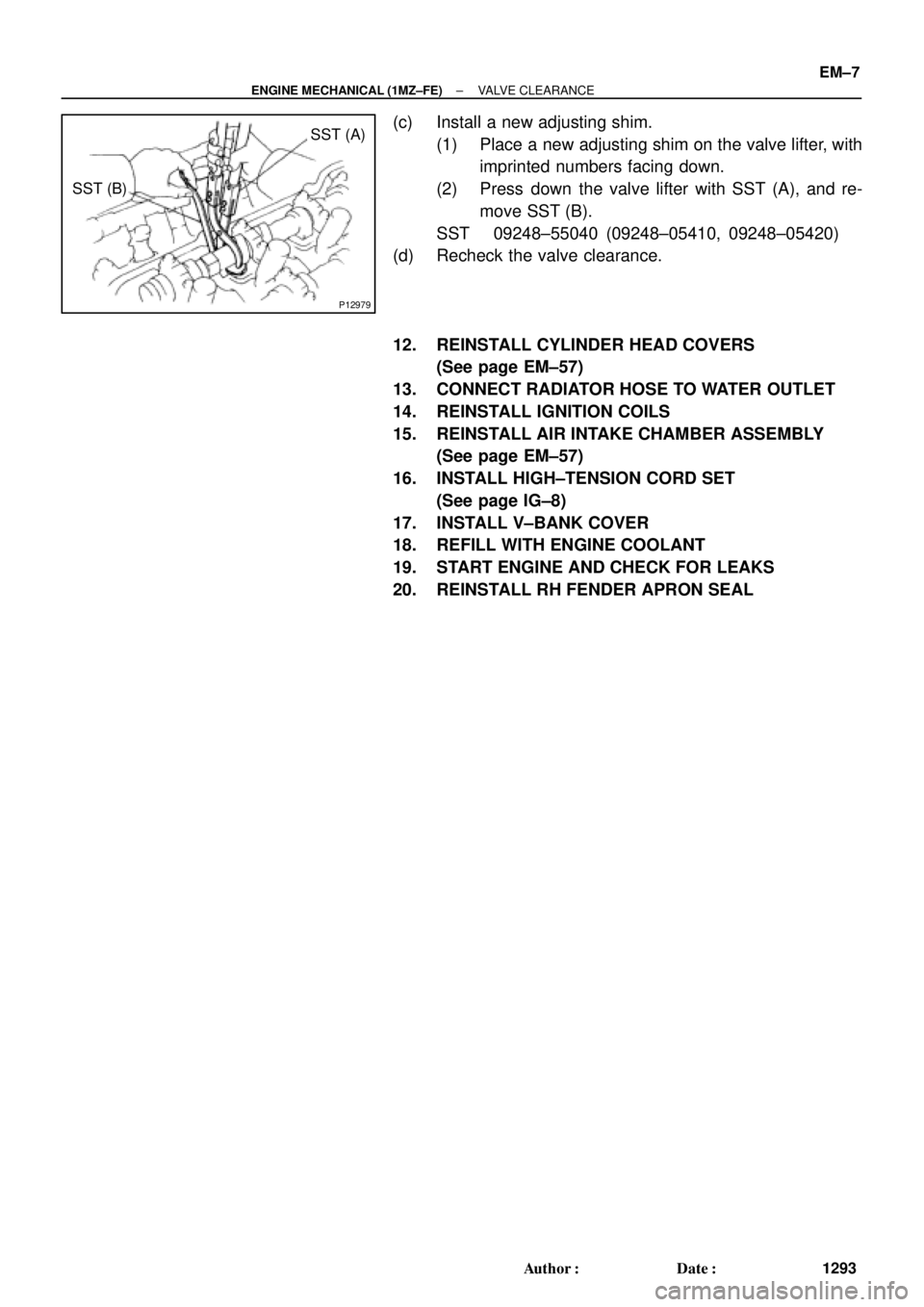
SST (A)
SST (B)
± ENGINE MECHANICAL (1MZ±FE)VALVE CLEARANCE
EM±7
1293 Author�: Date�:
(c) Install a new adjusting shim.
(1) Place a new adjusting shim on the valve lifter, with
imprinted numbers facing down.
(2) Press down the valve lifter with SST (A), and re-
move SST (B).
SST 09248±55040 (09248±05410, 09248±05420)
(d) Recheck the valve clearance.
12. REINSTALL CYLINDER HEAD COVERS
(See page EM±57)
13. CONNECT RADIATOR HOSE TO WATER OUTLET
14. REINSTALL IGNITION COILS
15. REINSTALL AIR INTAKE CHAMBER ASSEMBLY
(See page EM±57)
16. INSTALL HIGH±TENSION CORD SET
(See page IG±8)
17. INSTALL V±BANK COVER
18. REFILL WITH ENGINE COOLANT
19. START ENGINE AND CHECK FOR LEAKS
20. REINSTALL RH FENDER APRON SEAL