Page 3011 of 4770

F03952
SRLH
10
SR
R+
SFLR
SRRR
SRC2
AST
10
SFLR
SRRR
SRC2
AST Battery
MAIN
B±G1F4
ALT
1 B±G
F5
FL
Block
W±B
EA 3
333 2 ABS
12 Engine Room R/B No. 3
ABS & TRAC
Solenoid
Relay
16 33
3
4
5
W±L DLC1GR
GR±R
4A8ABS & TRAC ECU
ABS & TRAC ActuatorA7
A7
A7
A7
A7
A7
A7
A7
A7
A7
A7
A7
A89
10
12
11
3
4
6
5
7
2
8
1
5R±B
G±Y
L±B
W±R
W±R
LG±B
W±L
R±G
B±R
B±Y
Y±R
Y±B
R11
A15
1A15
13
A15
25
A15
2A17
8A17
26
A15
12
A15
1A17
7A17
5A17
4A17
12
A17
6A17
A15
SFLH
SRRH
SFRR
SRLR
SRC1
SMC1
SMC2 SFRH
F00057
1 2 3
4 5 6
7
8 9 10 11 12
A7
4
1 2 3
4 5 6
7
8 9 10 11 12
A7
4
1 2 3
4 5 6
7
8 9 10 11 12
A7
4
1 2 3
4 5 6
7
8 9 10 11 12
A7
4
1 2 3
4 5 6
7
8 9 10 11 12
A7
41 2 3
4 5 6
7
8 9 10 11 12A8
A74
± DIAGNOSTICSABS & TRACTION CONTROL SYSTEM
DI±591
826 Author�: Date�:
WIRING DIAGRAM
INSPECTION PROCEDURE
1 Check ABS & TRAC actuator solenoid.
PREPARATION:
Disconnect the 2 connectors from ABS & TRAC actuator.
CHECK:
Check continuity between terminals A8 ± 4 and A7 ± 1, 2, 3, 4,
5, 6, 7, 8, 9, 10, 11, 12 of ABS & TRAC actuator connector.
OK:
Continuity
HINT:
Resistance of each solenoid coil is 1.2 W.
NG Replace ABS & TRAC actuator.
OK
Page 3013 of 4770

BR3583
BR3582F00010
RotorSpeed Sensor
Magnet
To ECU
+V
±VHigh Speed
Low Speed
CoilNS
± DIAGNOSTICSABS & TRACTION CONTROL SYSTEM
DI±593
828 Author�: Date�:
DTC31, 32, 33, 34Speed Sensor Circuit
CIRCUIT DESCRIPTION
The speed sensor detects wheel speed and sends the ap-
propriate signals to the ECU. These signals are used to control
the ABS and TRAC system. The front and rear rotors each have
48 serrations.
When the rotors rotate, the magnetic field emitted by the perma-
nent magnet in the speed sensor generates an AC voltage.
Since the frequency of this AC voltage changes in direct propor-
tion to the speed of the rotor, the frequency is used by the ECU
to detect the speed of each wheel.
DTC No.DTC Detecting ConditionTrouble Area
31, 32, 33, 34
Detection of any of conditions from 1. through 3.:
1. ABS is in non±operation, wheel speed is 10 km/h or
more, one eighth of maximum wheel speed is greater
than the minimum wheel speed, one eighth of maximum
wheel speed is smaller than the rear maximum wheel
speed or momentary interruption of both the rear wheels
are shown in the 15 sec. or more continuously.
2. ABS is in non±operation, momentary interruption of
speed sensor occurs 7 times or more in the mean time
of switching the ignition switch ON and OFF or vehicle
speed is 20 km/h (12 mph) or more and the condition of
noise interference or non±noise interference occurs 75
times or more within 5 sec.
3. Vehicle is at a stop, malfunction signal of vehicle speed
sensor hardware open circuit is ON for 1.02 sec. contin-
uously since starting the checking of a certain vehicle.
�Right front, left front, right rear, left rear speed sensor
�Each speed sensor circuit
�Speed sensor rotor
�ECU
HINT:
�DTC No. 31 is for the right front speed sensor.
�DTC No. 32 is for the left front speed sensor.
�DTC No. 33 is for the right rear speed sensor.
�DTC No. 34 is for the left rear speed sensor.
Fail safe function:
If any trouble occurs in the speed sensor circuit, the ECU cuts off current to the ABS & TRAC solenoid relay
and prohibits ABS control and TRAC control.
DI1JP±03
Page 3344 of 4770
DI1KH±03
DI±924
± DIAGNOSTICSENGINE IMMOBILISER SYSTEM
1159 Author�: Date�:
DIAGNOSTIC TROUBLE CODE CHART
DTC No.
(See page)Detection ItemTrouble Area
B2795
(DI±928)Unmatched key code�Key
�Unregistered key inserted before
B2796
(DI±929)No communication in immobiliser system
�Key
�Transponder key coil
�Amplifier
�Wirehaness
�ECM
B2797
(DI±932)Communication malfunction No.1�Communication contests
�Unregistered key inserted before
B2798
(DI±935)Communication malfunction No.2
�Key
�Transponder key coil
�Amplifier
�Wirehaness
�ECM
HINT:
To reduce the unnecessary exchange of ECM, check that a trouble occurs with the original ECM at the time
of exchanging ECM and the trouble will disappear with a new ECM.
Page 3345 of 4770
DI1KI±04
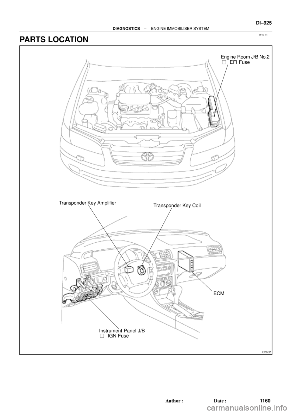
I02682
Engine Room J/B No.2
��EFI Fuse
Transponder Key Amplifier
Transponder Key Coil
ECM
��IGN Fuse Instrument Panel J/B
± DIAGNOSTICSENGINE IMMOBILISER SYSTEM
DI±925
1160 Author�: Date�:
PARTS LOCATION
Page 3347 of 4770

DI1KK±03
± DIAGNOSTICSENGINE IMMOBILISER SYSTEM
DI±927
1162 Author�: Date�:
PROBLEM SYMPTOMS TABLE
SymptomSuspect AreaSee page
Immobiliser is not set.
(Engine starts with key codes other than the registered key code.)2. ECMIN±31
Engine does not start.
1. Key
2. Wire harness
3. Transponder key coil
4. Amplifier
5. ECM*1
IN±31
BE±128
IN±31
Security indicator is always ON.
1. Security indicator
2. Wire harness
3. ECM*2
IN±31
IN±31
Security indicator is always ON.
(Although code has been registered in the automatic registration
mode, indicator is not OFF.)1. Wire harness
2. Transponder key coil
3. Amplifier
4. ECMIN±31
BE±128
IN±31
Security indicator is OFF
(When DTC of immobiliser is output)
1. Wire harness
2. Transponder key coil
3. Amplifier
4. ECMIN±31
BE±128
IN±31
Security indicator is OFF.
(When DTC of immobiliser is not output)1. Wire harness
2. ECMIN±31
IN±31
Security indicator is abnormally brinking.1. Wire harness
2. ECMIN±31
IN±31
*1 : Check that the key which did not start the engine has been registered and that it is possible to start with
other already registered key codes.
*2 : Finish the automatic registration mode because the mode might still remain.
Page 3349 of 4770
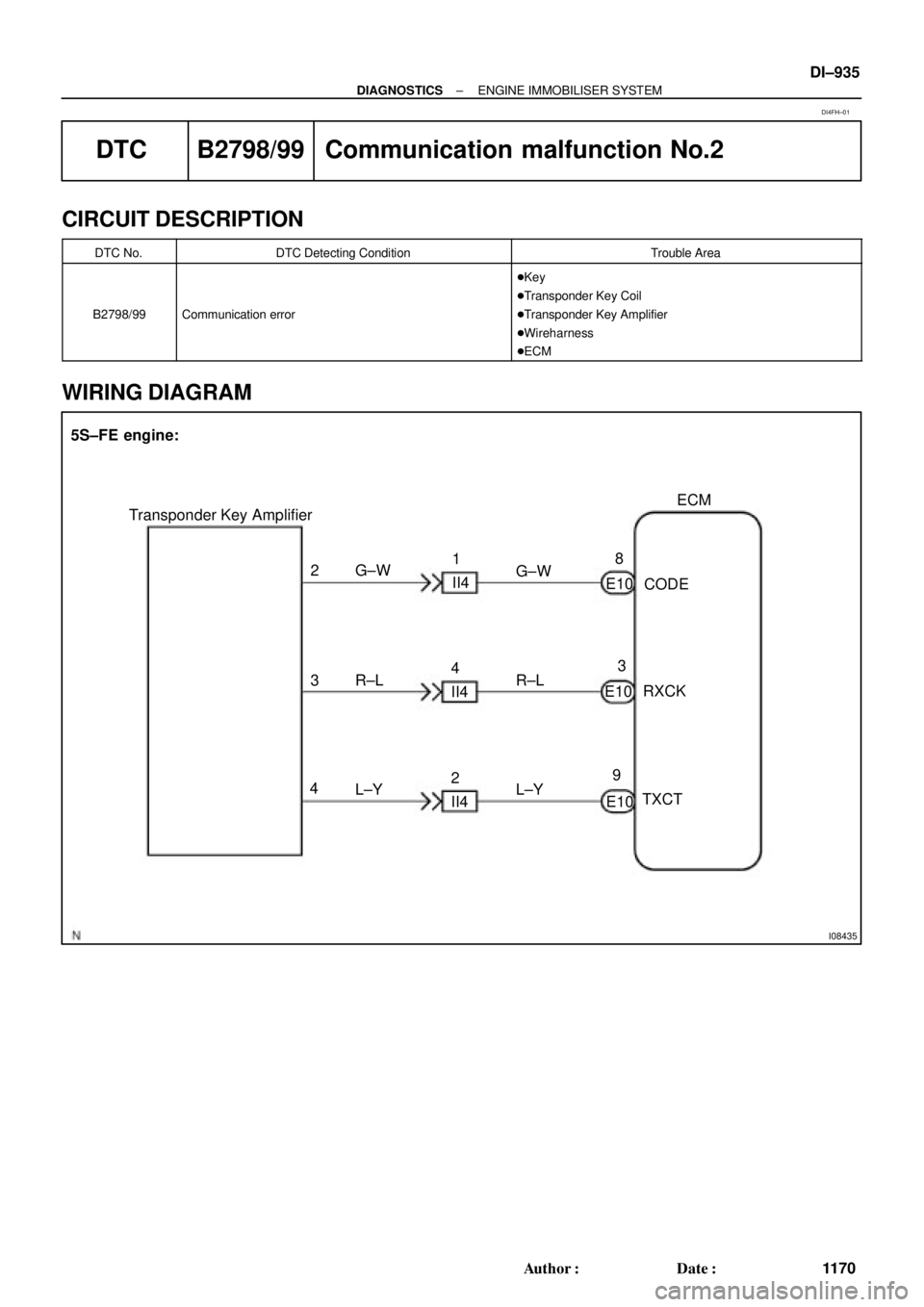
I08435
ECM
E10 28
93
E10
E10 3
4G±W
R±L
L±Y Transponder Key Amplifier
CODE
RXCK
TXCT 5S±FE engine:
G±W
R±L
L±Y 1
II4
4
II4
2
II4
± DIAGNOSTICSENGINE IMMOBILISER SYSTEM
DI±929
1164 Author�: Date�:
DTC B2796/99 No Communication in Immobiliser system
CIRCUIT DESCRIPTION
DTC No.DTC Detecting ConditionTrouble Area
B2796/99No communication
�Key
�Transponder Key Coil
�Transponder Key Amplifier
�Wireharness
�ECM
WIRING DIAGRAM
DI4FF±01
Page 3351 of 4770
± DIAGNOSTICSENGINE IMMOBILISER SYSTEM
DI±931
1166 Author�: Date�:
INSPECTION PROCEDURE
1 Check transponder key coil (See page BE±128).
NG Replace transponder key coil.
OK
2 Check harness and connector between transponder key amplifier and ECM.
NG Repair or replace harness and connector.
OK
3 Does it operate normally after replacement of transponder key amplifier?
Yes Replace transponder key amplifier.
No
Replace ECM.
Page 3355 of 4770
I08435
ECM
E10 28
93
E10
E10 3
4G±W
R±L
L±Y Transponder Key Amplifier
CODE
RXCK
TXCT 5S±FE engine:
G±W
R±L
L±Y 1
II4
4
II4
2
II4
± DIAGNOSTICSENGINE IMMOBILISER SYSTEM
DI±935
1170 Author�: Date�:
DTC B2798/99 Communication malfunction No.2
CIRCUIT DESCRIPTION
DTC No.DTC Detecting ConditionTrouble Area
B2798/99Communication error
�Key
�Transponder Key Coil
�Transponder Key Amplifier
�Wireharness
�ECM
WIRING DIAGRAM
DI4FH±01