Page 3357 of 4770
± DIAGNOSTICSENGINE IMMOBILISER SYSTEM
DI±937
1172 Author�: Date�:
INSPECTION PROCEDURE
1 Check transponder key coil (See page BE±128).
NG Replace transponder key coil
OK
2 Check harness and connector between transponder key amplifier and ECM.
NG Repair or replace harness and connector
OK
3 Does it operate normally after replacement of transponder key amplifier?
Yes Replace transponder key amplifier.
No
Replace ECM.
Page 3395 of 4770
COMPRESSION
EM±3
1175 Author�: Date�:
COMPRESSION
INSPECTION
HINT:
If there is lack of power, excessive oil consumption or poor fuel
ec")
EM07Y±05
S05312
Compression
Gauge
± ENGINE MECHANICAL (5S±FE)COMPRESSION
EM±3
1175 Author�: Date�:
COMPRESSION
INSPECTION
HINT:
If there is lack of power, excessive oil consumption or poor fuel
economy, measure the compression pressure.
1. WARM UP AND STOP ENGINE
Allow the engine to warm up to normal operating temperature.
2. DISCONNECT IGNITION COIL CONNECTORS
3. REMOVE SPARK PLUGS (See page IG±1)
4. INSPECT CYLINDER COMPRESSION PRESSURE
(a) Insert a compression gauge into the spark plug hole.
(b) Fully open the throttle.
(c) While cranking the engine, measure the compression
pressure.
HINT:
Always use a fully charged battery to obtain engine speed of
250 rpm or more.
(d) Repeat steps (a) through (c) for each cylinder.
NOTICE:
This measurement must be done in as short a time as pos-
sible.
Compression pressure:
1,226 kPa (12.5 kgf/cm
2, 178 psi) or more
Minimum pressure: 981 kPa (10.0 kgf/cm
2, 142 psi)
Difference between each cylinder:
98 kPa (1.0 kgf/cm
2, 14 psi) or less
(e) If the cylinder compression in one or more cylinders is low,
pour a small amount of engine oil into the cylinder through
the spark plug hole and repeat steps (a) through (c) for
cylinders with low compression.
�If adding oil helps the compression, it is likely that
the piston rings and/or cylinder bore are worn or
damaged.
�If pressure stays low, a valve may be sticking or
seating is improper, or there may be leakage past
the gasket.
5. REINSTALL SPARK PLUGS (See page IG±1)
6. RECONNECT IGNITION COIL CONNECTORS
Page 3403 of 4770

EM082±04
Z19417
TDCCrankshaft
Gear
No.1 Balance
Shaft Gear30°
AB
AB 1
2
3
4
100°
210°
280°
P06121
C C
Z19411
No.1 Balance ShaftMark B
Mark A
No.2 Housing
Z19413
No.1 Balance
Shaft
Mark B
Mark A No.2 Housing
± ENGINE MECHANICAL (5S±FE)BALANCE SHAFT BACKLASH
EM±11
1183 Author�: Date�:
BALANCE SHAFT BACKLASH
ON±VEHICLE INSPECTION
1. REMOVE OIL PAN AND OIL STRAINER
(See page LU±7)
2. INSPECT BACKLASH OF CRANKSHAFT GEAR AND
NO.1 BALANCE SHAFT GEAR
NOTICE:
Backlash between the crankshaft gear and No.1 balance
shaft gear varies with the rotation of the balance shaft and
the deviation of the crankshaft gear. Accordingly, it is nec-
essary to measure the backlash at the 4 points shown in
the illustration on the left.
(a) Turn the crankshaft 2 or 3 times to settle the crankshaft
gear and No.1 balance shaft gear.
(b) When No.1 piston is at TDC, check that the punch marks
C shown in the illustration of the balance shafts are
aligned with the grooves of the No.2 housing.
(c) Check that punch marks A and B are at the positions on
the No.1 balance shaft indicated in the illustration.
(d) First turn the crankshaft clockwise, and align the groove
of the No.2 balance shaft housing with punch mark A of
the No.1 balance shaft.
Page 3405 of 4770
BALANCE SHAFT BACKLASH
EM±13
1185 Author�: Date�:
(p) Turn the crankshaft clockw")
Z19415
No.1 Balance
Shaft
Mark B
Mark A
No.2 Housing
Z19408
2
46 153
Z19409
1
35 Pull
264
± ENGINE MECHANICAL (5S±FE)BALANCE SHAFT BACKLASH
EM±13
1185 Author�: Date�:
(p) Turn the crankshaft clockwise again to align the groove
of the No.2 housing with punch mark B.
(q) Set the dial indicator. (See step (e))
(r) Measure the backlash. (See step (f))
Standard backlash (at punch mark B):
0.025 ± 0.085 mm (0.0010 ± 0.0033 in.)
(s) Remove the dial indicator.
If even one of the 4 points measured above exceeds the back-
lash specification, adjust the backlash with new spacers.
NOTICE:
Use the same size spacers for both the left and right sides.
HINT:
�Varying the spacer thickness by 0.02 mm (0.0008 in.)
changes the backlash by about 0.014 mm (0.0006 in.).
�If the backlash is greater than the permitted maximum,
select a thinner shim.
�If the backlash is less than the specification, select a thick-
er shim.
3. REPLACE NEW SPACERS
(a) Uniformly loosen the 6 bolts in the sequence shown.
(b) Replace the spacers with new ones.
4. TIGHTEN BALANCE SHAFT ASSEMBLY
While pulling the center part of the engine balancer in the direc-
tion of the arrow, uniformly tighten the 6 bolts in several passes,
in the sequence shown.
Torque: 49 N´m (500 kgf´cm, 36 ft´lbf)
5. INSPECT AND ADJUST BACKLASH OF CRANK-
SHAFT GEAR AND NO.1 BALANCE SHAFT GEAR
(See step 2)
6. REINSTALL OIL STRAINER AND OIL PAN
(See page LU±13)
Page 3408 of 4770
S05937
No.2 Timing Belt
Cover
No.1 Timing Belt
Cover
Tension Spring Crankshaft
Pulley
Camshaft Timing Pulley
No.1 Idler Pulley
No.2 Idler Pulley
Oil Pump Pulley
Crankshaft Timing Pulley Wire ClampWire ClampWire ClampSpark Plug High±Tension CordTiming Belt Guide Timing Belt
*
1 Gasket Wire
ClampGenerator Wire
Generator Connector
Generator
Wire
Clamp
N´m (kgf´cm, ft´lbf)
*
2 For use with SST
42 (425, 31)
42 (425, 31)
24 (245, 18)18 (180, 13) 108 (1,100, 80)
54 (550, 40)
*
2
37 (380, 27)
: Specified torque*
1 Gasket
*
1
Replace only if damaged EM±16
± ENGINE MECHANICAL (5S±FE)TIMING BELT
1188 Author�: Date�:
Page 3413 of 4770
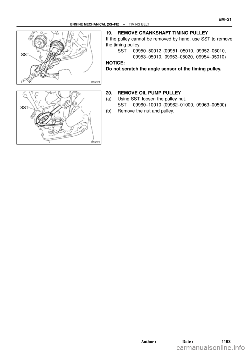
S05579
SST
S05575
SST
± ENGINE MECHANICAL (5S±FE)TIMING BELT
EM±21
1193 Author�: Date�:
19. REMOVE CRANKSHAFT TIMING PULLEY
If the pulley cannot be removed by hand, use SST to remove
the timing pulley.
SST 09950±50012 (09951±05010, 09952±05010,
09953±05010, 09953±05020, 09954±05010)
NOTICE:
Do not scratch the angle sensor of the timing pulley.
20. REMOVE OIL PUMP PULLEY
(a) Using SST, loosen the pulley nut.
SST 09960±10010 (09962±01000, 09963±00500)
(b) Remove the nut and pulley.
Page 3414 of 4770
TIMING BELT
1194 Author�: Date�:
INSPECTION
1. INSPECT TIMING BELT
NOTICE:
�Do not bend, twist or turn the t")
EM085±03
EM3336
No!
S01519
Turn
Seal
P15243Free Length EM±22
± ENGINE MECHANICAL (5S±FE)TIMING BELT
1194 Author�: Date�:
INSPECTION
1. INSPECT TIMING BELT
NOTICE:
�Do not bend, twist or turn the timing belt inside out.
�Do not allow the timing belt to come into contact with
oil, water or steam.
�Do not utilize timing belt tension when installing or re-
moving the mounting bolt of the camshaft timing
pulley.
If there are any defects as shown in the illustration, check these
points:
(a) Premature parting
�Check for proper installation.
�Check the timing cover gasket for damage and
proper installation.
(b) If the belt teeth are cracked or damaged, check to see if
either camshaft or water pump is locked.
(c) If there is noticeable wear or cracks on the belt face,
check to see if there are nicks on the side of the idler
pulley lock.
(d) If there is wear or damage on only one side of the belt,
check the belt guide and the alignment of each pulley.
(e) If there is noticeable wear on the belt teeth, check the tim-
ing cover for damage and check gasket has been
installed correctly and for foreign material on the pulley
teeth.
If necessary, replace the timing belt.
2. INSPECT IDLER PULLEYS
(a) Visually check the seal portion of the idler pulley for oil
leakage.
If leakage is found, replace the idler pulley.
(b) Check that the idler pulley turns smoothly.
If necessary, replace the idler pulley.
3. INSPECT TENSION SPRING
(a) Measure the free length of tension spring.
Free length: 42.0 mm (1.654 in.)
If the free length is not as specified, replace the tension spring.
(b) Measure the tension of the tension spring at the specified
installed length.
Installed tension (at 50.5 mm (1.988 in.)):
32 ± 37 N (3.25 ± 3.75 kgf, 7.2 ± 8.3 lbf)
If the installed tension is not as specified, replace the tension
spring.
Page 3415 of 4770
TIMING BELT
EM±23
1195 Author�: Date�:
INSTALLATION
1. INSTALL OIL PUMP PULLEY
(")
EM086±04
S05576
SST
S05577
Angle
Sensor
Inward
S05571
35 mm
S05616
42 mm
S05926
Pry
Move
± ENGINE MECHANICAL (5S±FE)TIMING BELT
EM±23
1195 Author�: Date�:
INSTALLATION
1. INSTALL OIL PUMP PULLEY
(a) Align the cutouts of the pulley and shaft, and slide on the
pulley.
(b) Using SST, install the pulley nut.
SST 09960±10010 (09962±01000, 09963±00500)
Torque: 24 N´m (245 kgf´cm, 18 ft´lbf)
2. INSTALL CRANKSHAFT TIMING PULLEY
(a) Align the timing pulley set key with the key groove of the
pulley.
(b) Slide on the timing pulley, facing the angle sensor inward.
NOTICE:
Do not scratch the angle sensor of the timing pulley.
3. INSTALL NO.2 IDLER PULLEY
(a) Install the pulley with the bolt.
Torque: 42 N´m (425 kgf´cm, 31 ft´lbf)
HINT:
Use the 35 mm (1.38 in.) long bolt.
(b) Check that the idler pulley moves smoothly.
4. TEMPORARILY INSTALL NO.1 IDLER PULLEY AND
TENSION SPRING
(a) Align the bracket pin hole with the pivot pin.
(b) Install the pulley with the bolt. Do not tighten the bolt yet.
HINT:
Use the 42 mm (1.65 in.) long bolt.
(c) Install the tension spring.
(d) Pry the pulley toward the left as far as it will go, and tighten
the bolt.
(e) Check that the idler pulley moves smoothly.