Page 3562 of 4592
W03088
SA0028
A: Inside
B: Outside AB
Front BA SA±6
± SUSPENSION AND AXLEFRONT WHEEL ALIGNMENT
1957 Author�: Date�:
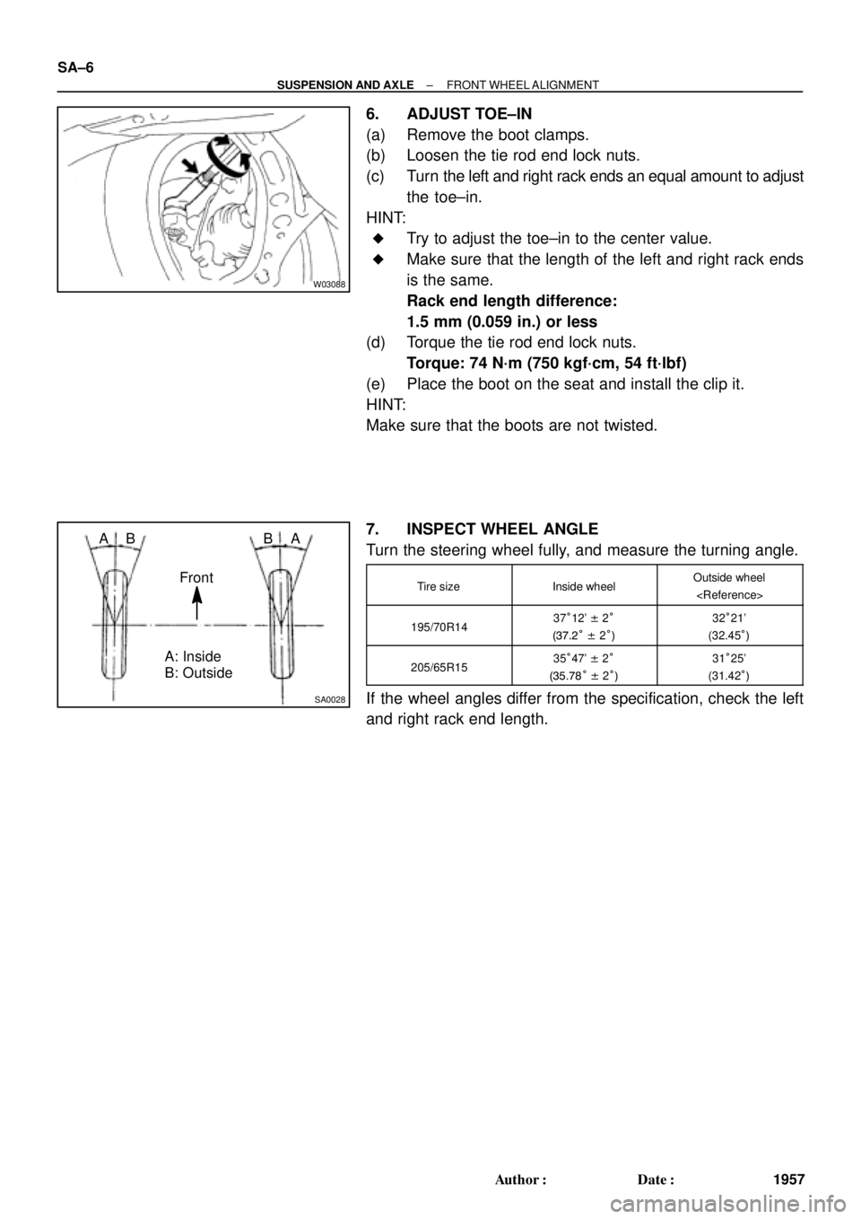
6. ADJUST TOE±IN
(a) Remove the boot clamps.
(b) Loosen the tie rod end lock nuts.
(c) Turn the left and right rack ends an equal amount to adjust
the toe±in.
HINT:
�Try to adjust the toe±in to the center value.
�Make sure that the length of the left and right rack ends
is the same.
Rack end length difference:
1.5 mm (0.059 in.) or less
(d) Torque the tie rod end lock nuts.
Torque: 74 N´m (750 kgf´cm, 54 ft´lbf)
(e) Place the boot on the seat and install the clip it.
HINT:
Make sure that the boots are not twisted.
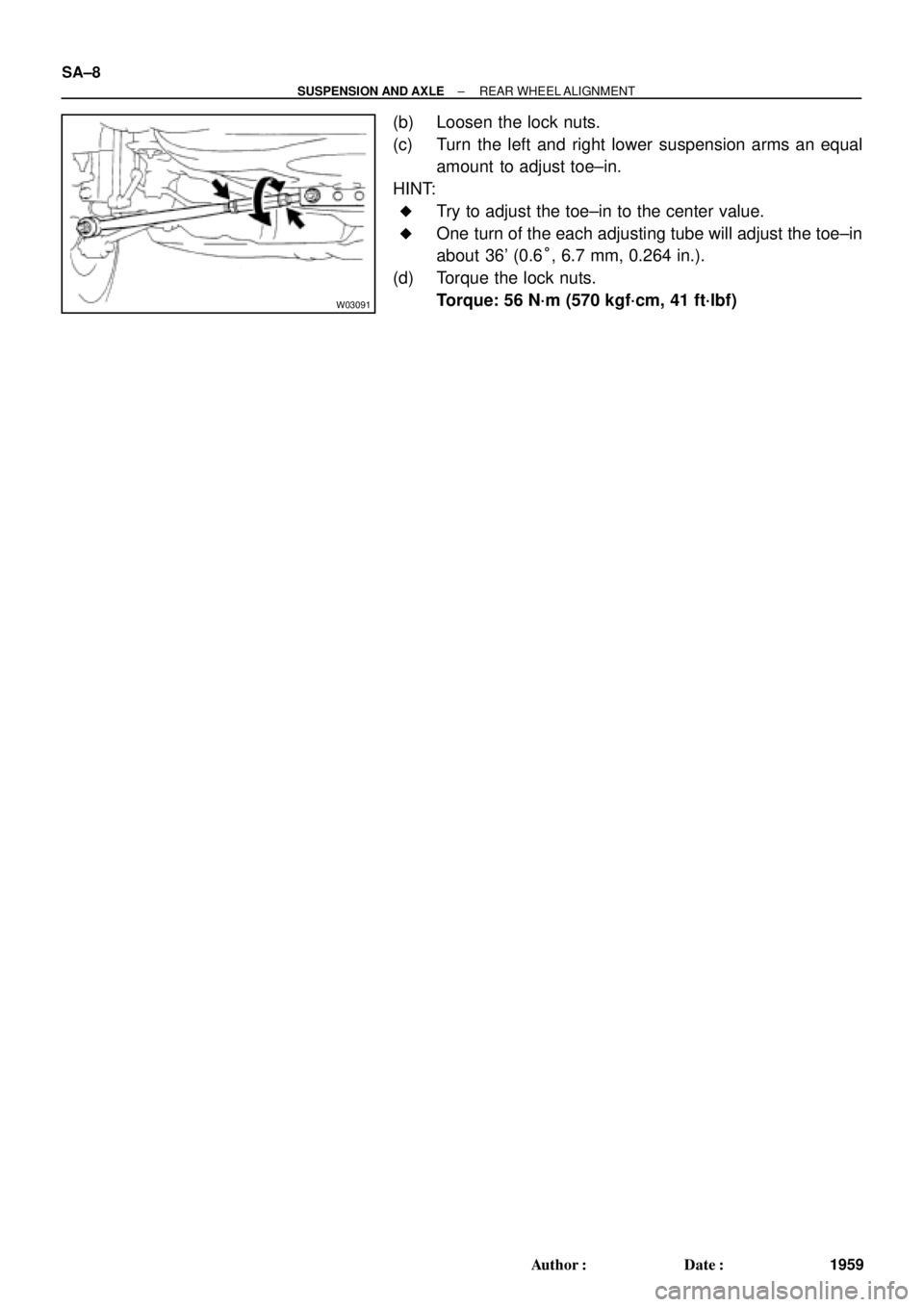
7. INSPECT WHEEL ANGLE
Turn the steering wheel fully, and measure the turning angle.
Tire sizeInside wheelOutside wheel
195/70R1437°12' ± 2°
(37.2° ± 2°)32°21'
(32.45°)
205/65R1535°47' ± 2°
(35.78° ± 2°)31°25'
(31.42°)
If the wheel angles differ from the specification, check the left
and right rack end length.
Page 3564 of 4592
W03091
SA±8
± SUSPENSION AND AXLEREAR WHEEL ALIGNMENT
1959 Author�: Date�:
(b) Loosen the lock nuts.
(c) Turn the left and right lower suspension arms an equal
amount to adjust toe±in.
HINT:
�Try to adjust the toe±in to the center value.
�One turn of the each adjusting tube will adjust the toe±in
about 36' (0.6°, 6.7 mm, 0.264 in.).
(d) Torque the lock nuts.
Torque: 56 N´m (570 kgf´cm, 41 ft´lbf)
Page 3565 of 4592
SA07B±01
W03092
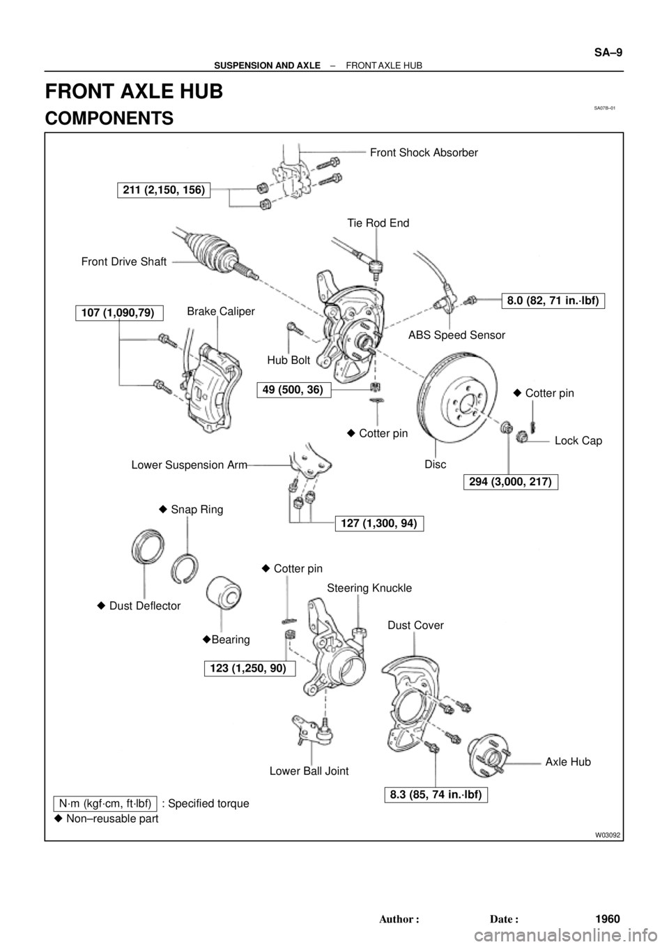
Front Shock Absorber
Tie Rod End
Front Drive Shaft
Brake Caliper
ABS Speed Sensor
Lower Suspension ArmLock Cap
� Snap Ring
� Dust DeflectorSteering Knuckle
Dust Cover
�Bearing
Lower Ball JointAxle Hub
127 (1,300, 94)
294 (3,000, 217)
107 (1,090,79)
8.0 (82, 71 in.´lbf)
123 (1,250, 90)� Cotter pin� Cotter pin� Cotter pin Hub Bolt
Disc
N´m (kgf´cm, ft´lbf) : Specified torque
� Non±reusable part
211 (2,150, 156)
49 (500, 36)
8.3 (85, 74 in.´lbf)
± SUSPENSION AND AXLEFRONT AXLE HUB
SA±9
1960 Author�: Date�:
FRONT AXLE HUB
COMPONENTS
Page 3566 of 4592

2. CHECK BE")
SA07C±01
W03084W03084
W03093
W03139
W03094
SST
SA±10
± SUSPENSION AND AXLEFRONT AXLE HUB
1961 Author�: Date�:
REMOVAL
1. REMOVE FRONT WHEEL
Torque: 103 N´m (1,050 kgf´cm, 76 ft´lbf)
2. CHECK BEARING BACKLASH AND AXLE HUB DEVI-
ATION
(a) Remove the 2 bolts, brake caliper and disc.
(b) Support the brake caliper securely.
(c) Using a dial indicator near the center of the axle hub and
check the backlash in the bearing shaft direction.
Maximum: 0.05 mm (0.0020 in.)
If the backlash exceeds the maximum, replace the bearing.
(d) Using a dial indicator, check the deviation at the surface
of the axle hub outside the hub bolt.
Maximum: 0.05 mm (0.0020 in.)
If the deviation exceeds the maximum, replace the bearing.
(e) Install the disc, 2 bolts and brake caliper.
Torque: 107 N´m (1,090 kgf´cm, 79 ft´lbf)
3. REMOVE DRIVE SHAFT LOCK NUT
(a) Remove the cotter pin and lock cap.
(b) With applying the brakes, remove the nut.
Torque: 294 N´m (3,000 kgf´cm, 217 ft´lbf)
(c) Remove the brake caliper and disc.
4. w/ ABS:
REMOVE ABS SPEED SENSOR AND WIRE HARNESS
CLAMP
Torque: 8.0 N´m (82 kgf´cm, 71 in.´lbf)
5. LOOSEN 2 NUTS ON LOWER SIDE OF SHOCK AB-
SORBER
Torque: 211 N´m (2,150 kgf´cm, 156 ft´lbf)
HINT:
�Do not remove the bolts.
�At the time of installation, coat the nut's thread with en-
gine oil.
6. DISCONNECT TIE ROD END FROM STEERING
KNUCKLE
(a) Remove the cotter pin and nut.
Torque: 49 N´m (500 kgf´cm, 36 ft´lbf)
(b) Using SST, disconnect the tie rod end from the steering
knuckle.
SST 09610±20012
Page 3567 of 4592
W03095
± SUSPENSION AND AXLEFRONT AXLE HUB
SA±11
1962 Author�: Date�:
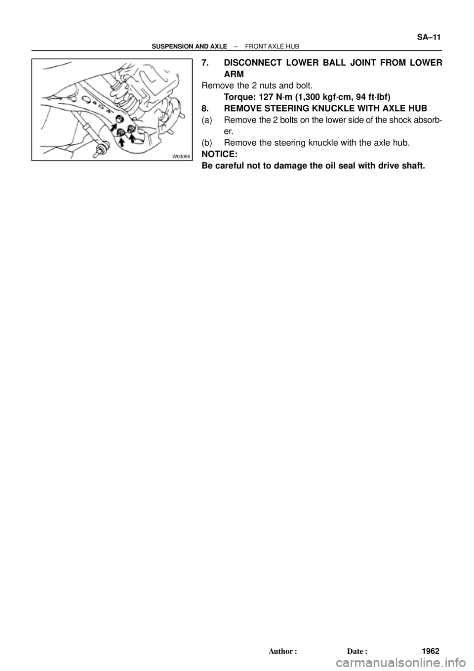
7. DISCONNECT LOWER BALL JOINT FROM LOWER
ARM
Remove the 2 nuts and bolt.
Torque: 127 N´m (1,300 kgf´cm, 94 ft´lbf)
8. REMOVE STEERING KNUCKLE WITH AXLE HUB
(a) Remove the 2 bolts on the lower side of the shock absorb-
er.
(b) Remove the steering knuckle with the axle hub.
NOTICE:
Be careful not to damage the oil seal with drive shaft.
Page 3569 of 4592
SA07E±01
R00792
SST
R08860
SST
SST
Z19236
SST
SST
± SUSPENSION AND AXLEFRONT AXLE HUB
SA±13
1964 Author�: Date�:
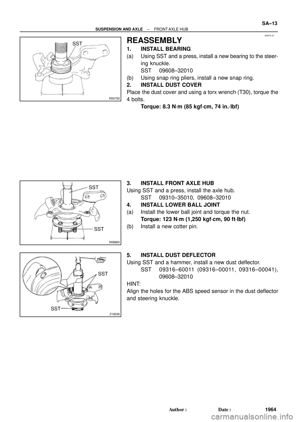
REASSEMBLY
1. INSTALL BEARING
(a) Using SST and a press, install a new bearing to the steer-
ing knuckle.
SST 09608±32010
(b) Using snap ring pliers, install a new snap ring.
2. INSTALL DUST COVER
Place the dust cover and using a torx wrench (T30), torque the
4 bolts.
Torque: 8.3 N´m (85 kgf´cm, 74 in.´lbf)
3. INSTALL FRONT AXLE HUB
Using SST and a press, install the axle hub.
SST 09310±35010, 09608±32010
4. INSTALL LOWER BALL JOINT
(a) Install the lower ball joint and torque the nut.
Torque: 123 N´m (1,250 kgf´cm, 90 ft´lbf)
(b) Install a new cotter pin.
5. INSTALL DUST DEFLECTOR
Using SST and a hammer, install a new dust deflector.
SST 09316±60011 (09316±00011, 09316±00041),
09608±32010
HINT:
Align the holes for the ABS speed sensor in the dust deflector
and steering knuckle.
Page 3571 of 4592
W03096
SST
SA07G±01
W03097
± SUSPENSION AND AXLEFRONT WHEEL HUB BOLT
SA±15
1966 Author�: Date�:
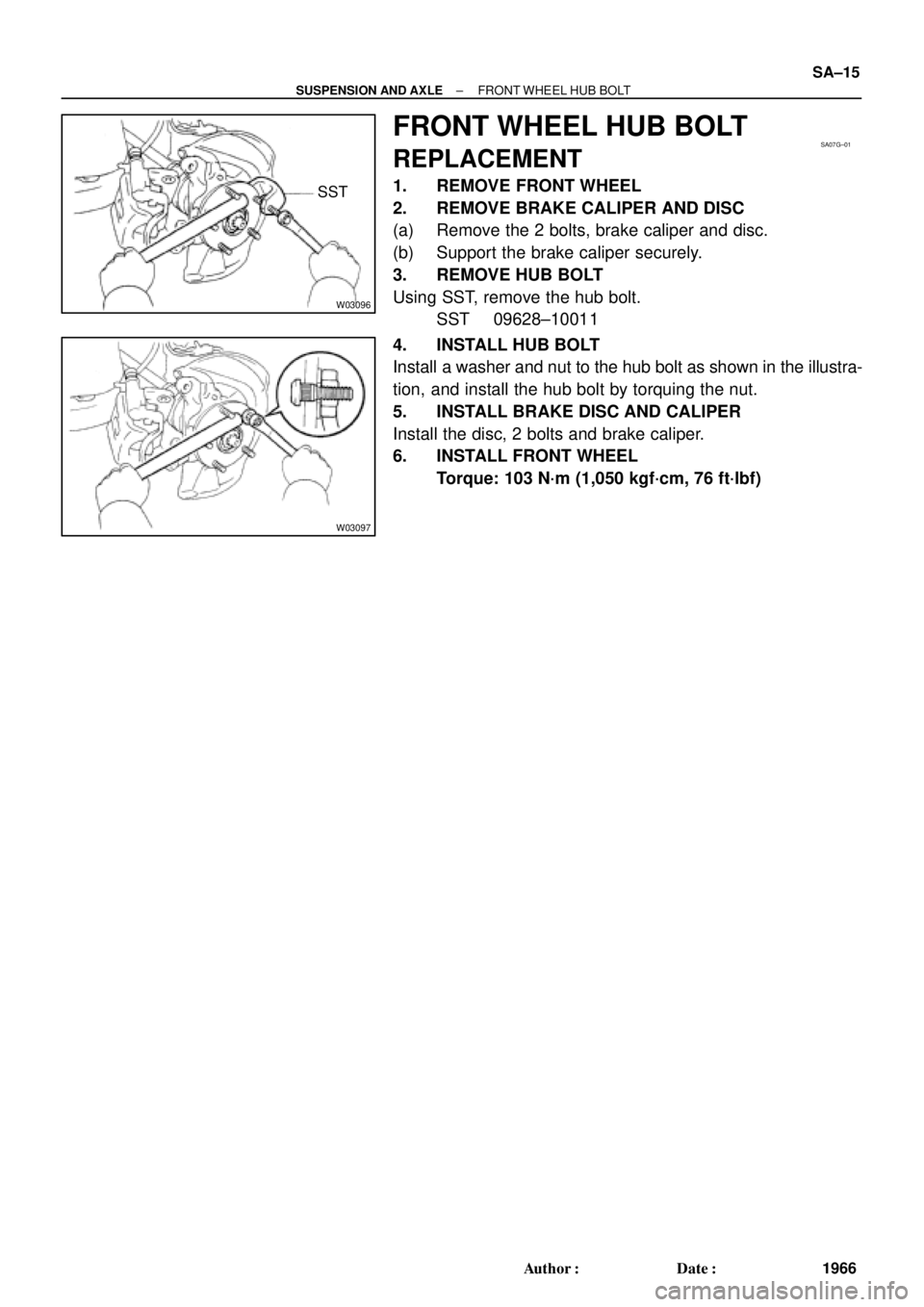
FRONT WHEEL HUB BOLT
REPLACEMENT
1. REMOVE FRONT WHEEL
2. REMOVE BRAKE CALIPER AND DISC
(a) Remove the 2 bolts, brake caliper and disc.
(b) Support the brake caliper securely.
3. REMOVE HUB BOLT
Using SST, remove the hub bolt.
SST 09628±10011
4. INSTALL HUB BOLT
Install a washer and nut to the hub bolt as shown in the illustra-
tion, and install the hub bolt by torquing the nut.
5. INSTALL BRAKE DISC AND CALIPER
Install the disc, 2 bolts and brake caliper.
6. INSTALL FRONT WHEEL
Torque: 103 N´m (1,050 kgf´cm, 76 ft´lbf)
Page 3572 of 4592
SA08P±01
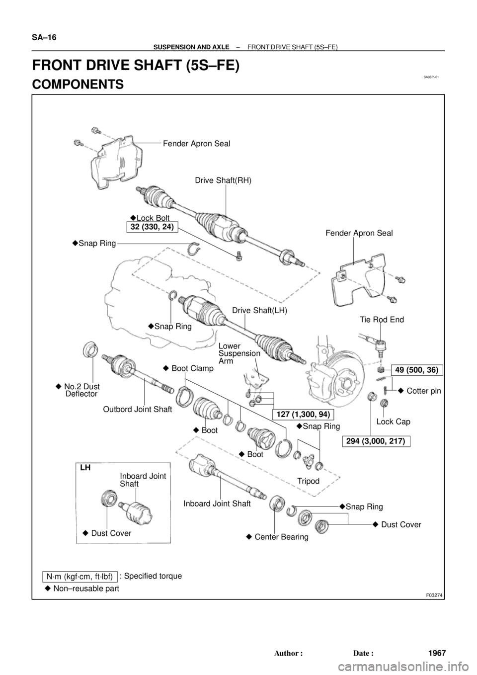
F03274
Fender Apron Seal
Drive Shaft(RH)
Fender Apron Seal �Lock Bolt
�Snap Ring
Tie Rod End
Lower
Suspension
Arm
� Boot Clamp
Outbord Joint Shaft � No.2 Dust
Deflector�Snap RingDrive Shaft(LH)
�Snap Ring
�Snap Ring � Boot
� Boot
294 (3,000, 217)� Cotter pin
Lock Cap
Tripod
� Dust Cover
� Center Bearing Inboard Joint Shaft Shaft Inboard Joint
� Dust Cover LH
N´m (kgf´cm, ft´lbf): Specified torque
� Non±reusable part
49 (500, 36)
127 (1,300, 94)
32 (330, 24)
SA±16
± SUSPENSION AND AXLEFRONT DRIVE SHAFT (5S±FE)
1967 Author�: Date�:
FRONT DRIVE SHAFT (5S±FE)
COMPONENTS