Page 3573 of 4592

SA±17
1968 Author�: Date�:
REMOVAL
NOTICE:
The hub bearing could be damaged if it is subjected to the
vehicle weig")
SA08Q±01
FA1535
SST
W03093
W03142
± SUSPENSION AND AXLEFRONT DRIVE SHAFT (5S±FE)
SA±17
1968 Author�: Date�:
REMOVAL
NOTICE:
The hub bearing could be damaged if it is subjected to the
vehicle weight, such as when moving the vehicle with the
drive shaft removed.
Therefore, if it is absolutely necessary to place the vehicle
weight on the hub bearing, first support it with SST.
SST 09608±16042 (09608±02021, 09608±02041)
1. REMOVE FRONT WHEEL AND FRONT FENDER
APRON SEAL
Torque: 103 N´m (1,050 kgf´cm, 76 ft´lbf)
2. REMOVE DRIVE SHAFT LOCK NUT
(a) Remove the cotter pin and lock cap.
(b) With applying the brakes, remove the nut.
Torque: 294 N´m (3,000 kgf´cm, 217 ft´lbf)
3. DRAIN GEAR OIL (M/T) or ATF (A/T)
4. DISCONNECT TIE ROD END FROM STEERING
KNUCKLE (See page SA±10)
5. DISCONNECT LOWER BALL JOINT FROM LOWER
SUSPENSION ARM (See page SA±10)
6. DISCONNECT DRIVE SHAFT FROM AXLE HUB
(a) Using a plastic hammer, disconnect the drive shaft from
the axle hub.
NOTICE:
Cover the drive shaft boot with cloth to protect it from dam-
age.
(b) Push the front axle hub toward the outside of the vehicle,
and separate the drive shaft from the axle hub.
Page 3574 of 4592

1969 Author�: Date�:
7. REMOVE LH DRIVE SHAFT
(a) Using a brass bar and hammer, remove the drive shaft.
HINT:
At the time of")
W03143
LH
W03144
RH SA±18
± SUSPENSION AND AXLEFRONT DRIVE SHAFT (5S±FE)
1969 Author�: Date�:
7. REMOVE LH DRIVE SHAFT
(a) Using a brass bar and hammer, remove the drive shaft.
HINT:
At the time of installation, please refer to the following items.
�Coat gear oil to the inboard joint shaft and differen-
tial case sliding surface.
�Before installing the drive shaft, set the snap ring
with its opening side facing downward.
�Whether or not the inboard joint shaft is making con-
tact with the pinion shaft can be known by the sound
or feeling when driving it in.
�After installation, check that there is 2 ± 3 mm (0.08
± 0.12 in.) of play in the axial direction.
�After installation, check that the drive shaft cannot
be removed by hand.
(b) Using a screwdriver, remove the snap ring from the in-
board joint shaft.
8. REMOVE RH DRIVE SHAFT
(a) Remove the bearing lock bolt.
Torque: 32 N´m (330 kgf´cm, 24 ft´lbf)
(b) Using pliers, remove the snap ring and drive shaft.
HINT:
At the time of installation, coat gear oil to the inboard joint shaft
and differential case sliding surface.
Page 3581 of 4592
SA07H±01
W03141
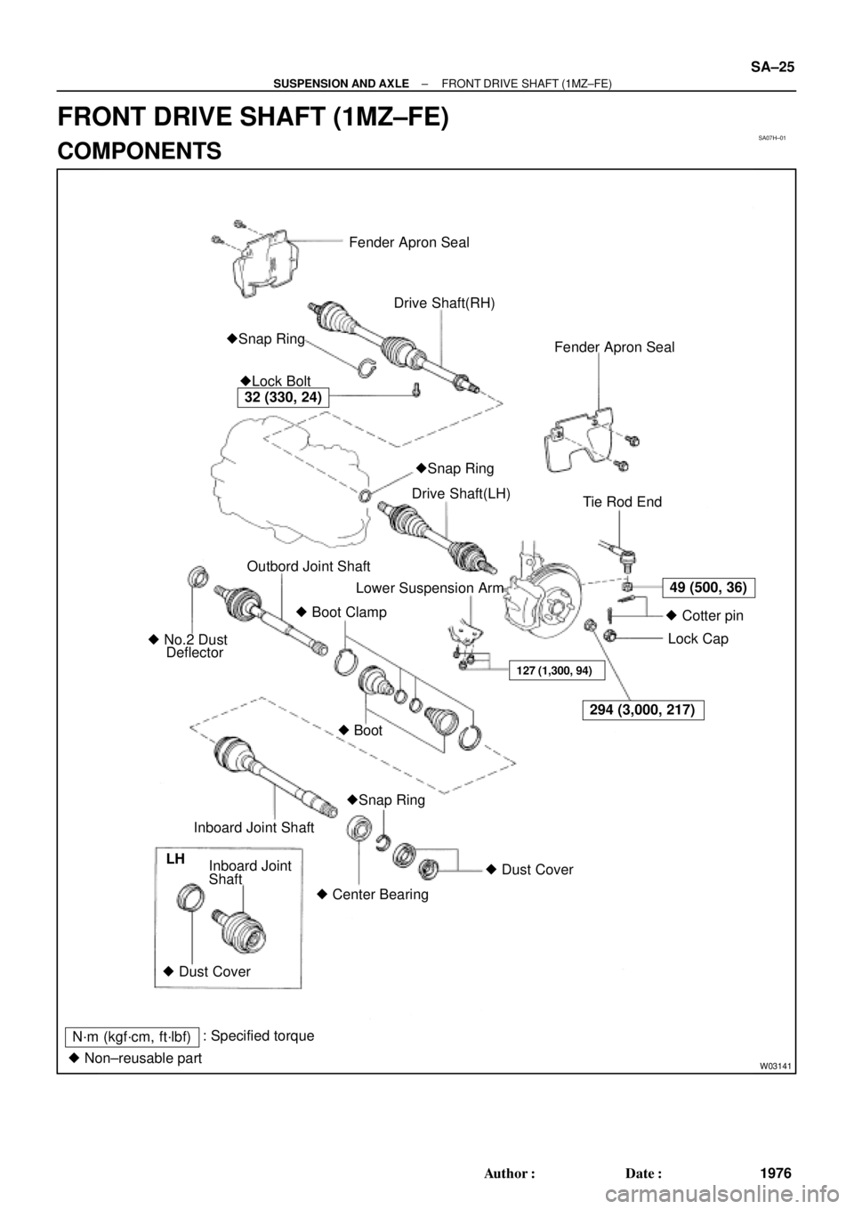
Fender Apron Seal
Drive Shaft(RH)
Fender Apron Seal
�Lock Bolt �Snap Ring
Tie Rod End
Lower Suspension Arm
� Boot Clamp Outbord Joint Shaft
� No.2 Dust
DeflectorDrive Shaft(LH)
�Snap Ring � Boot
32 (330, 24)
49 (500, 36)
294 (3,000, 217)
127 (1,300, 94)
� Cotter pin
Lock Cap
� Dust Cover
� Center Bearing Inboard Joint Shaft
Shaft Inboard Joint
� Dust Cover LH
N´m (kgf´cm, ft´lbf): Specified torque
� Non±reusable part�Snap Ring
± SUSPENSION AND AXLEFRONT DRIVE SHAFT (1MZ±FE)
SA±25
1976 Author�: Date�:
FRONT DRIVE SHAFT (1MZ±FE)
COMPONENTS
Page 3589 of 4592
SA07M±05
F06530
Suspension Support
Spring Bumper
Link Stabilizer Bar
Shock
Absorber
ABS Speed Sensor
Wire Harness ClampFront Drive Shaft with Coil SpringUpper Seat Bearing
Lower
Insulator
Lower Suspension Arm Lower Suspension
Bushing StopperBrake CaliperInsulator UpperSpring Support No. 2Suspension
Shock Absorber
Coil Spring
Tie Rod End
� Dust
Deflector
� Cotter Pin
� Cotter Pin� Cotter
Pin
Lower Ball jointDisc
Lock Cap ABS Speed Sensor
N´m (kgf´cm, ft´lbf): Specified torque
� Non±reusable part�
80 (820, 59)49 (500, 36)
39 (400, 29)
211 (2,150, 156)
107 (1,090, 79)
29 (300, 22)
123 (1,250, 90)49 (500, 36)
8.0 (82, 71 in.´lbf)
294 (3,000, 217)
206 (2,100, 152)
206 (2,100, 152)
206 (2,100, 152)
127 (1,300, 94)
127 (1,300, 94)
± SUSPENSION AND AXLEFRONT SHOCK ABSORBER
SA±33
1984 Author�: Date�:
FRONT SHOCK ABSORBER
COMPONENTS
Page 3590 of 4592

2. REMOVE FLEXIBLE HOSE AN")
SA07N±01
Z19346
To Outside SA±34
± SUSPENSION AND AXLEFRONT SHOCK ABSORBER
1985 Author�: Date�:
REMOVAL
1. REMOVE FRONT WHEEL
Torque: 103 N´m (1,050 kgf´cm, 76 ft´lbf)
2. REMOVE FLEXIBLE HOSE AND ABS SPEED SEN-
SOR WIRE HARNESS (w/ ABS) AND CLAMP FROM
SHOCK ABSORBER
Remove the bolt, flexible hose and ABS wire harness clamp.
Torque: 29 N´m (300 kgf´cm, 22 ft´lbf)
3. DISCONNECT STABILIZER BAR LINK FROM SHOCK
ABSORBER (See page SA±48)
4. DISCONNECT SHOCK ABSORBER FROM STEERING
KNUCKLE
(a) Remove the 2 nuts and bolts on the lower side of the
shock absorber.
Torque: 211 N´m (2,150 kgf´cm, 156 ft´lbf)
(b) Remove the shock absorber from the steering knuckle.
HINT:
At the time of installation, coat the nut's threads with engine oil.
5. REMOVE SHOCK ABSORBER WITH COIL SPRING
Remove the 3 nuts, suspension support No.2 and shock ab-
sorber with the coil spring.
Torque: 80 N´m (820 kgf´cm, 59 ft´lbf)
HINT:
At the time of installation rotate the suspension support and set
it in the direction, as shown in the illustration.
Page 3594 of 4592

SA07R±01
W03200
SST
W03201
W03199
SST SA±38
± SUSPENSION AND AXLEFRONT SHOCK ABSORBER
1989 Author�: Date�:
REASSEMBLY
1. INSTALL LOWER INSULATOR ONTO SHOCK AB-
SORBER
2. INSTALL SPRING BUMPER TO PISTON ROD
3. INSTALL COIL SPRING
(a) Using SST, compress the coil spring.
SST 09727±30021
NOTICE:
Do not use an impact wrench. It will damage the SST.
HINT:
Use 2 of the same type of SST.
(b) Install the coil spring to the shock absorber.
HINT:
Fit the lower end of the coil spring into the gap of the spring low-
er seat.
4. INSTALL SPRING UPPER SEAT AND INSULATOR
(a) Align the 'OUT' mark of spring upper seat with the mark
of the upper insulator.
(b) Install the spring upper seat with upper insulator to the
shock absorber with the mark facing the outside of the ve-
hicle.
(c) Install the bearing and suspension support.
(d) Using SST to hold the suspension support, install a new
nut.
SST 09729±22031
Torque: 49 N´m (500 kgf´cm, 36 ft´lbf)
(e) Remove the SST from the coil spring.
SST 09727±30021
NOTICE:
Check that the bearing fits into the recess in the suspen-
sion support.
Page 3596 of 4592
SA07T±04
F06530
Suspension Support
Spring Bumper
Link Stabilizer Bar
Shock
Absorber
ABS Speed Sensor
Wire Harness ClampFront Drive Shaft with Coil SpringUpper Seat Bearing
Lower
Insulator
Lower Suspension Arm Lower Suspension
Bushing StopperBrake CaliperInsulator UpperSpring Support No. 2Suspension
Shock Absorber
Coil Spring
Tie Rod End
� Dust
Deflector
� Cotter Pin
� Cotter Pin� Cotter
Pin
Lower Ball jointDisc
Lock Cap ABS Speed Sensor
N´m (kgf´cm, ft´lbf): Specified torque
� Non±reusable part�
80 (820, 59)49 (500, 36)
39 (400, 29)
211 (2,150, 156)
107 (1,090, 79)
29 (300, 22)
123 (1,250, 90)49 (500, 36)
8.0 (82, 71 in.´lbf)
294 (3,000, 217)
206 (2,100, 152)
206 (2,100, 152)
206 (2,100, 152)
127 (1,300, 94)
127 (1,300, 94)
SA±40
± SUSPENSION AND AXLEFRONT LOWER SUSPENSION ARM
1991 Author�: Date�:
FRONT LOWER SUSPENSION ARM
COMPONENTS
Page 3597 of 4592
SA07U±01
W03202
W03203
W03204
± SUSPENSION AND AXLEFRONT LOWER SUSPENSION ARM
SA±41
1992 Author�: Date�:
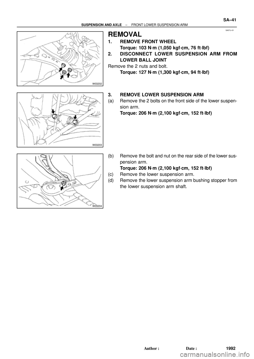
REMOVAL
1. REMOVE FRONT WHEEL
Torque: 103 N´m (1,050 kgf´cm, 76 ft´lbf)
2. DISCONNECT LOWER SUSPENSION ARM FROM
LOWER BALL JOINT
Remove the 2 nuts and bolt.
Torque: 127 N´m (1,300 kgf´cm, 94 ft´lbf)
3. REMOVE LOWER SUSPENSION ARM
(a) Remove the 2 bolts on the front side of the lower suspen-
sion arm.
Torque: 206 N´m (2,100 kgf´cm, 152 ft´lbf)
(b) Remove the bolt and nut on the rear side of the lower sus-
pension arm.
Torque: 206 N´m (2,100 kgf´cm, 152 ft´lbf)
(c) Remove the lower suspension arm.
(d) Remove the lower suspension arm bushing stopper from
the lower suspension arm shaft.