Page 3609 of 4592
 w/ Drum brake:
Remove the bolt, and disconnect the flexible hose from
the shock absorber.
Torque: 29 N´m (300")
A
B
A
W03211
R11165
± SUSPENSION AND AXLEREAR AXLE HUB
SA±53
2004 Author�: Date�:
(c) w/ Drum brake:
Remove the bolt, and disconnect the flexible hose from
the shock absorber.
Torque: 29 N´m (300 kgf´cm, 22 ft´lbf)
(d) Support the backing plate securely.
6. w/ ABS:
REMOVE ABS SPEED SENSOR
Torque: 8.0 N´m (82 kgf´cm, 71 in.´lbf)
7. REMOVE REAR AXLE CARRIER
(a) Loosen the 3 nuts.
Torque:
Nut A:
Reused nut: 196 N´m (2,000 kgf´cm, 145 ft´lbf)
New nut: 255 N´m (2,600 kgf´cm, 188 ft´lbf)
Nut B: 181 N´m (1,850 kgf´cm, 134 ft´lbf)
HINT:
At the time of installation, please refer to the following items.
�If reusing the 2 nuts, coat the nut's threads with en-
gine oil.
�After stabilizing the suspension, torque the nuts.
(b) Remove the bolt and nut, and disconnect the strut rod
from the rear axle carrier.
NOTICE:
When removing/installing bolt, stop the nut from rotating
and loosen/torque the bolt.
Torque: 113 N´m (1,150 kgf´cm, 83 ft´lbf)
(c) Remove the 2 nuts and bolts on the lower side of the
shock absorber.
(d) Remove the nut, bolt and No.2 lower suspension arm.
(e) Remove the rear axle carrier.
Page 3611 of 4592
Z00212
SST
SA088±01
Z00213
± SUSPENSION AND AXLEREAR WHEEL HUB BOLT
SA±55
2006 Author�: Date�:
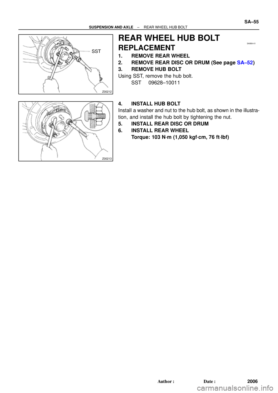
REAR WHEEL HUB BOLT
REPLACEMENT
1. REMOVE REAR WHEEL
2. REMOVE REAR DISC OR DRUM (See page SA±52)
3. REMOVE HUB BOLT
Using SST, remove the hub bolt.
SST 09628±10011
4. INSTALL HUB BOLT
Install a washer and nut to the hub bolt, as shown in the illustra-
tion, and install the hub bolt by tightening the nut.
5. INSTALL REAR DISC OR DRUM
6. INSTALL REAR WHEEL
Torque: 103 N´m (1,050 kgf´cm, 76 ft´lbf)
Page 3612 of 4592
SA089±01
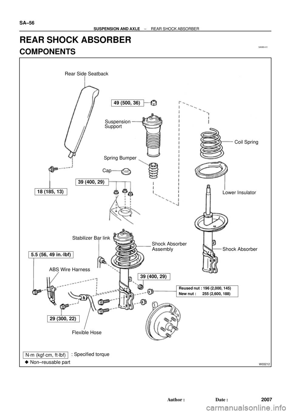
W03212
Spring Bumper
Lower Insulator
N´m (kgf´cm, ft´lbf): Specified torque
� Non±reusable partSuspension
Support
Coil Spring
Stabilizer Bar link
Assembly Shock Absorber Rear Side Seatback
Cap
Shock Absorber
ABS Wire Harness
Flexible Hose
49 (500, 36)
5.5 (56, 49 in.´lbf)
39 (400, 29)
29 (300, 22)
39 (400, 29)
Reused nut : 196 (2,000, 145)
New nut : 255 (2,600, 188)
18 (185, 13) SA±56
± SUSPENSION AND AXLEREAR SHOCK ABSORBER
2007 Author�: Date�:
REAR SHOCK ABSORBER
COMPONENTS
Page 3613 of 4592

2. REMOVE REAR WHEEL
Torque: 103")
SA08A±01
R00749
R10288
W03213
± SUSPENSION AND AXLEREAR SHOCK ABSORBER
SA±57
2008 Author�: Date�:
REMOVAL
1. REMOVE REAR SIDE SEATBACK
(See page BO±113 or BO±118)
2. REMOVE REAR WHEEL
Torque: 103 N´m (1,050 kgf´cm, 76 ft´lbf)
3. REMOVE FLEXIBLE HOSE AND ABS SPEED SEN-
SOR WIRE HARNESS (w/ ABS) FROM SHOCK AB-
SORBER
Remove the 2 bolts, flexible hose bracket and ABS wire har-
ness clamp.
Torque:
Flexible hose: 29 N´m (300 kgf´cm, 22 ft´lbf)
ABS wire: 5.5 N´m (56 kgf´cm, 49 in.´lbf)
4. DISCONNECT STABILIZER BAR LINK FROM SHOCK
ABSORBER (See page SA±70)
5. REMOVE SHOCK ABSORBER WITH COIL SPRING
(a) Loosen the 2 nuts on the lower side of the shock absorber.
Torque:
Reused nut: 196 N´m (2,000 kgf´cm, 145 ft´lbf)
New nut: 255 N´m (2,600 kgf´cm, 188 ft´lbf)
HINT:
At the time of installation, coat the nut's threads with engine oil.
(b) Support the rear axle carrier with a jack.
(c) Remove the cap.
(d) Loosen the nut in the middle of the suspension support.
NOTICE:
Do not remove it.
Torque: 49 N´m (500 kgf´cm, 36 ft´lbf)
(e) Remove the 3 nuts of the suspension support.
Torque: 39 N´m (400 kgf´cm, 29 ft´lbf)
(f) Lower the rear axle carrier and remove the 2 bolts.
(g) Remove the shock absorber with the coil spring.
Page 3619 of 4592
SA08G±01
56 (570, 41)
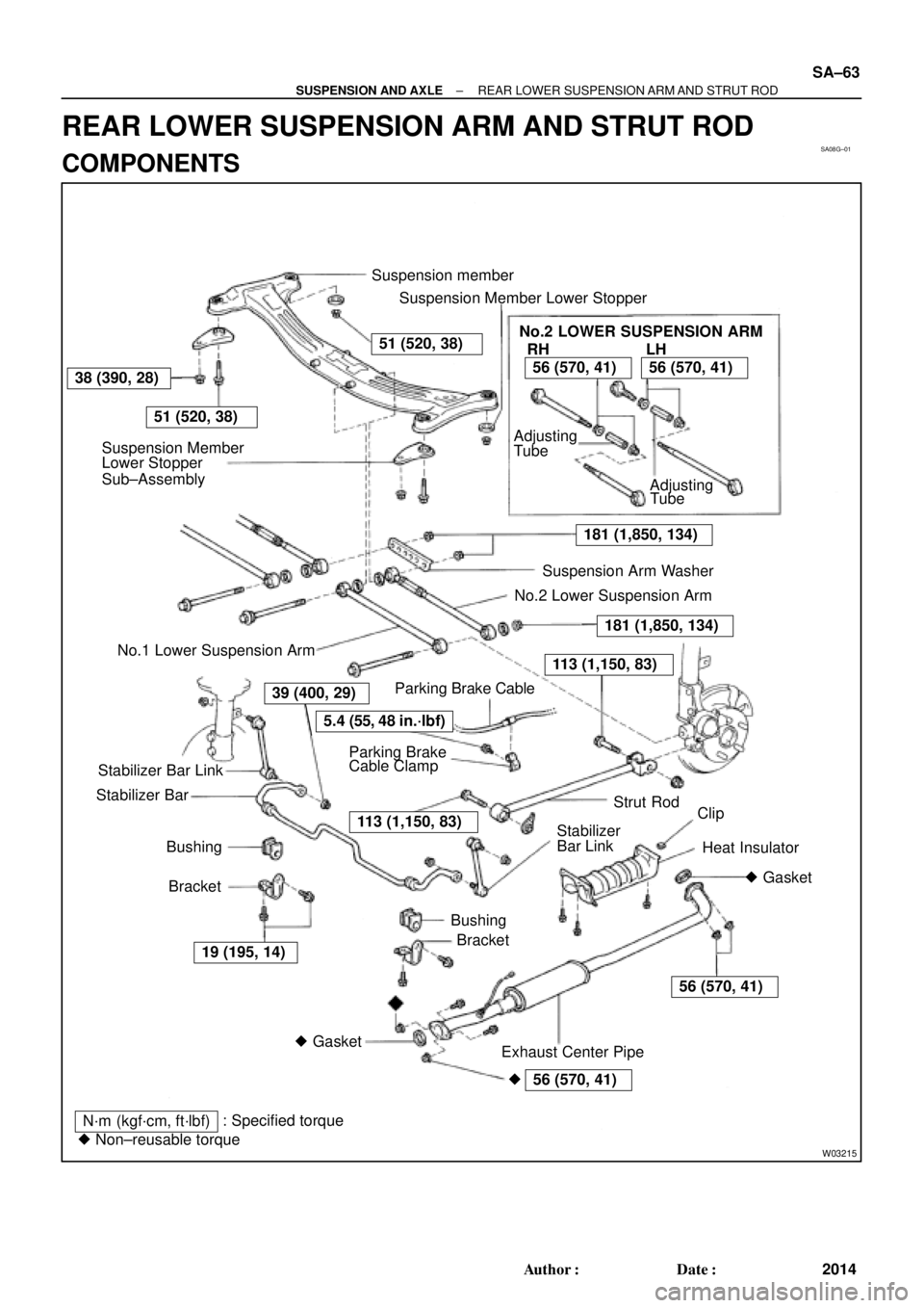
W03215
Suspension member
Suspension Member Lower Stopper
Suspension Member
Lower Stopper
Sub±Assembly
N´m (kgf´cm, ft´lbf): Specified torque
� Non±reusable torqueStabilizer Bar
Bracket Bushing
Bracket Bushing Stabilizer Bar Link
Exhaust Center PipeClip
Heat Insulator Strut Rod Parking BrakeSuspension Arm Washer
No.2 Lower Suspension Arm
No.1 Lower Suspension Arm
Stabilizer
� Gasket AdjustingNo.2 LOWER SUSPENSION ARM
RH
Tube
Adjusting
Tube
� GasketBar Link Cable Clamp
51 (520, 38)
51 (520, 38)
LH
181 (1,850, 134)
38 (390, 28)56 (570, 41)56 (570, 41)
181 (1,850, 134)
113 (1,150, 83)
5.4 (55, 48 in.´lbf)
39 (400, 29)
113 (1,150, 83)
56 (570, 41)
19 (195, 14)Parking Brake Cable
�
± SUSPENSION AND AXLEREAR LOWER SUSPENSION ARM AND STRUT ROD
SA±63
2014 Author�: Date�:
REAR LOWER SUSPENSION ARM AND STRUT ROD
COMPONENTS
Page 3620 of 4592

SA08H±01
W03216
W03217
Rear
W03219A B
A B SA±64
± SUSPENSION AND AXLEREAR LOWER SUSPENSION ARM AND STRUT ROD
2015 Author�: Date�:
REMOVAL
1. REMOVE REAR WHEEL
Torque: 103 N´m (1,050 kgf´cm, 76 ft´lbf)
2. REMOVE EXHAUST CENTER PIPE
5S±FE Engine: (See page EM±114)
1MZ±FE Engine: (See page EM±111)
3. REMOVE STRUT ROD
(a) Remove the bolt and disconnect the parking brake cable.
Torque: 5.4 N´m (55 kgf´cm, 48 in.´lbf)
(b) Remove the 2 bolts and nuts.
Torque: 113 N´m (1,150 kgf´cm, 83 ft´lbf)
HINT:
At the time of installtion,after stabilizing the suspension, torque
the bolts.
(c) Remove the strut rod.
4. REMOVE NO.2 LOWER SUSPENSION ARM
(a) Remove the 3 nuts, suspension arm washer and wash-
ers.
Torque: 181 N´m (1,850 kgf´cm, 134 ft´lbf)
HINT:
At the time of installtion, after stabilizing the suspension, torque
the nuts.
(b) Remove the No.2 lower suspension arm.
HINT:
At the time of installtion, face the paint mark to the rearward.
5. REMOVE LEFT AND RIGHT STABILIZER BRACKETS
(See page SA±70)
6. REMOVE NO.1 LOWER SUSPENSION ARM
(a) Support the suspension member with a jack.
(b) Remove the 4 nuts, 2 bolts and suspension member low-
er stoppers.
Torque:
Bolt: 51 N´m (520 kgf´cm, 38 ft´lbf)
Nut A: 51 N´m (520 kgf´cm, 38 ft´lbf)
Nut B: 38 N´m (390 kgf´cm, 28 ft´lbf)
(c) Lower the suspension member.
Page 3623 of 4592
SA08J±01
W03222
W03223
AB
W03224
± SUSPENSION AND AXLEREAR LOWER SUSPENSION ARM AND STRUT ROD
SA±67
2018 Author�: Date�:
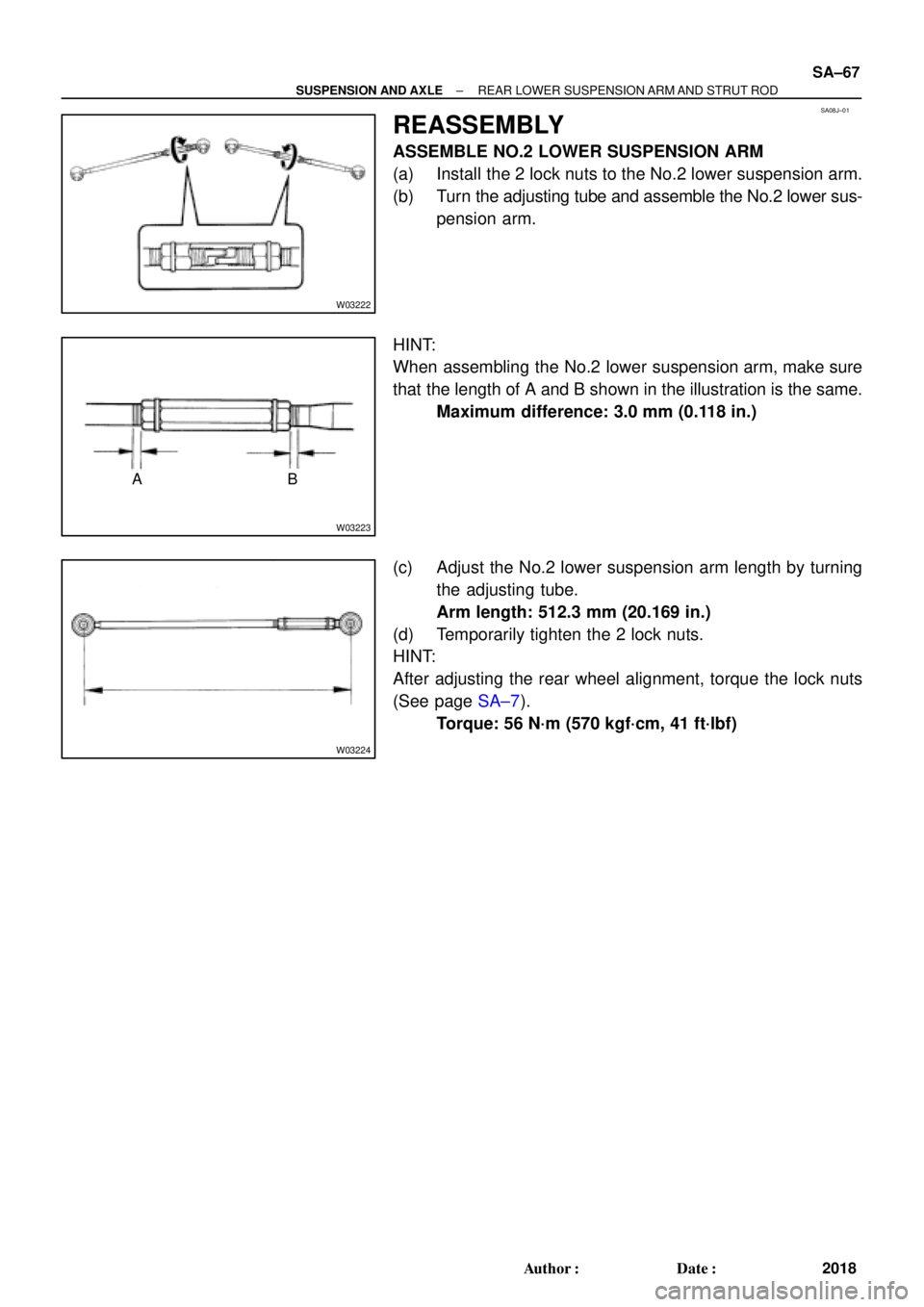
REASSEMBLY
ASSEMBLE NO.2 LOWER SUSPENSION ARM
(a) Install the 2 lock nuts to the No.2 lower suspension arm.
(b) Turn the adjusting tube and assemble the No.2 lower sus-
pension arm.
HINT:
When assembling the No.2 lower suspension arm, make sure
that the length of A and B shown in the illustration is the same.
Maximum difference: 3.0 mm (0.118 in.)
(c) Adjust the No.2 lower suspension arm length by turning
the adjusting tube.
Arm length: 512.3 mm (20.169 in.)
(d) Temporarily tighten the 2 lock nuts.
HINT:
After adjusting the rear wheel alignment, torque the lock nuts
(See page SA±7).
Torque: 56 N´m (570 kgf´cm, 41 ft´lbf)
Page 3625 of 4592
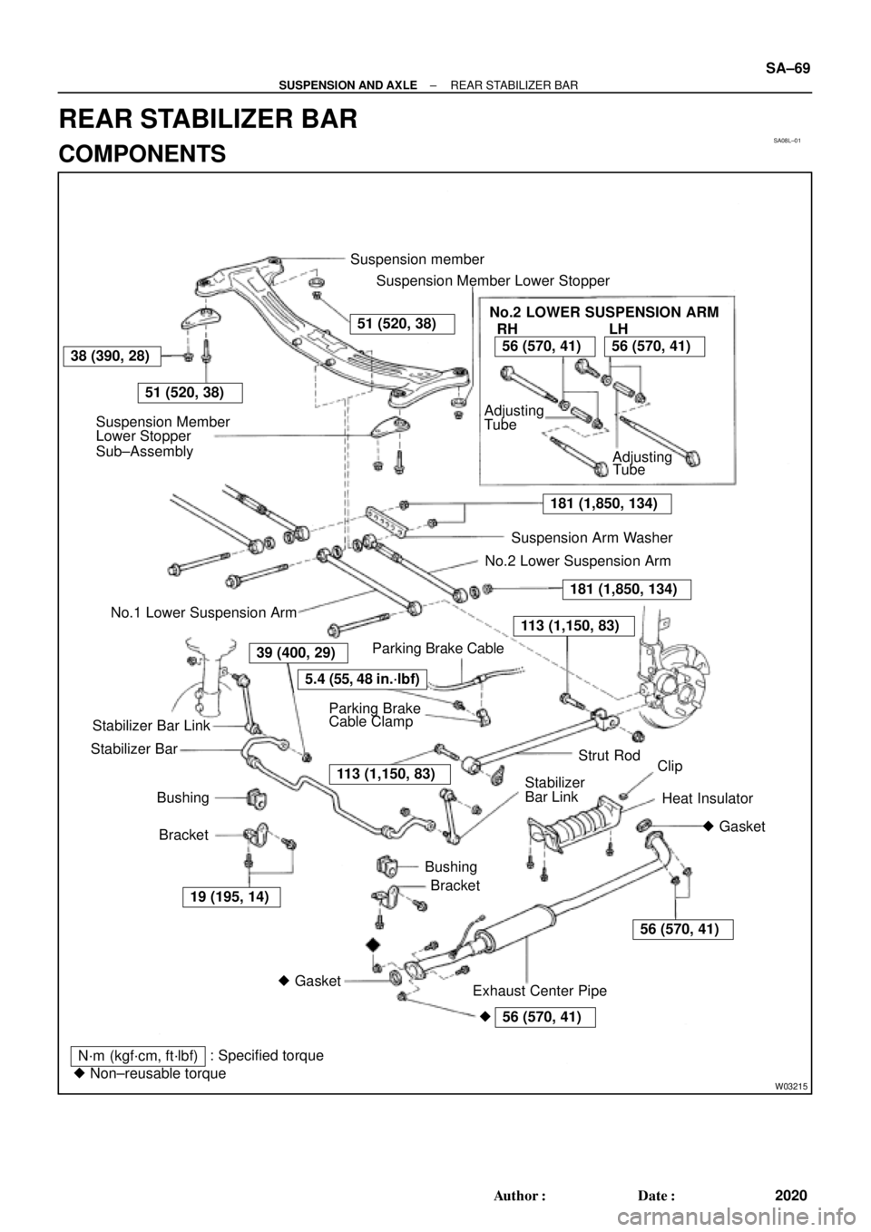
SA08L±01
56 (570, 41)
W03215
Suspension member
Suspension Member Lower Stopper
Suspension Member
Lower Stopper
Sub±Assembly
N´m (kgf´cm, ft´lbf): Specified torque
� Non±reusable torqueStabilizer Bar
Bracket Bushing
Bracket Bushing Stabilizer Bar Link
Exhaust Center PipeClip
Heat Insulator Strut Rod Parking BrakeSuspension Arm Washer
No.2 Lower Suspension Arm
No.1 Lower Suspension Arm
Stabilizer
� Gasket AdjustingNo.2 LOWER SUSPENSION ARM
RH
Tube
Adjusting
Tube
� GasketBar Link Cable Clamp
51 (520, 38)
51 (520, 38)
LH
181 (1,850, 134)
38 (390, 28)56 (570, 41)56 (570, 41)
181 (1,850, 134)
113 (1,150, 83)
5.4 (55, 48 in.´lbf)
39 (400, 29)
113 (1,150, 83)
56 (570, 41)
19 (195, 14)Parking Brake Cable
�
± SUSPENSION AND AXLEREAR STABILIZER BAR
SA±69
2020 Author�: Date�:
REAR STABILIZER BAR
COMPONENTS