Page 3626 of 4592
SA08M±01
W03225
W03226
SA±70
± SUSPENSION AND AXLEREAR STABILIZER BAR
2021 Author�: Date�:
REMOVAL
1. REMOVE REAR WHEELS
Torque: 103 N´m (1,050 kgf´cm, 76 ft´lbf)
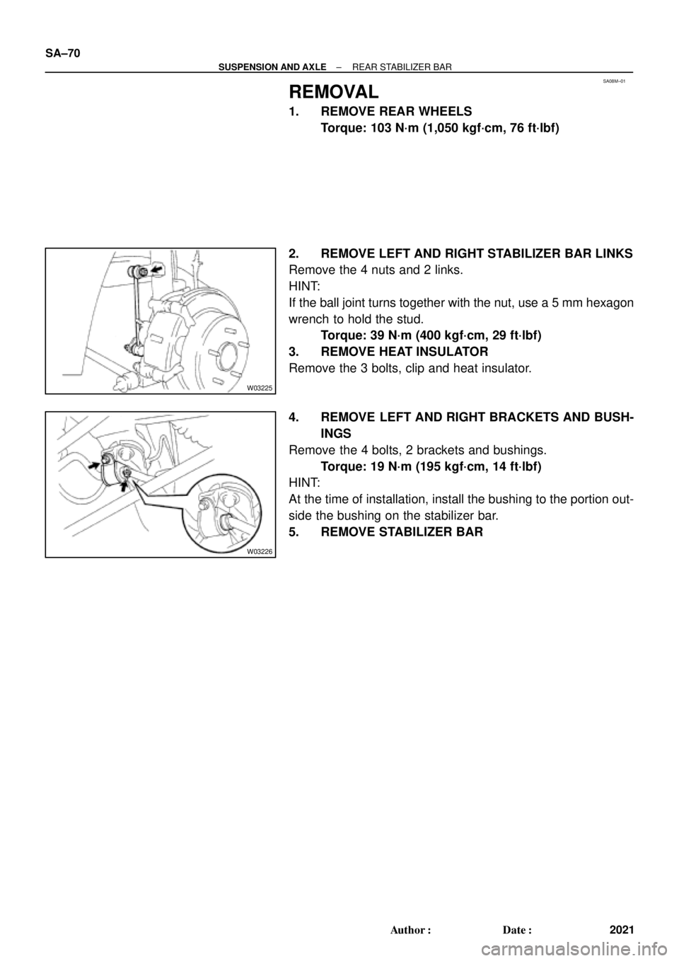
2. REMOVE LEFT AND RIGHT STABILIZER BAR LINKS
Remove the 4 nuts and 2 links.
HINT:
If the ball joint turns together with the nut, use a 5 mm hexagon
wrench to hold the stud.
Torque: 39 N´m (400 kgf´cm, 29 ft´lbf)
3. REMOVE HEAT INSULATOR
Remove the 3 bolts, clip and heat insulator.
4. REMOVE LEFT AND RIGHT BRACKETS AND BUSH-
INGS
Remove the 4 bolts, 2 brackets and bushings.
Torque: 19 N´m (195 kgf´cm, 14 ft´lbf)
HINT:
At the time of installation, install the bushing to the portion out-
side the bushing on the stabilizer bar.
5. REMOVE STABILIZER BAR
Page 3627 of 4592
SA08N±01
Z00340
± SUSPENSION AND AXLEREAR STABILIZER BAR
SA±71
2022 Author�: Date�:
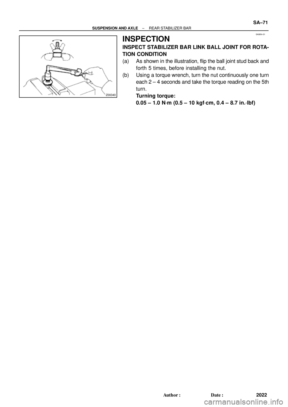
INSPECTION
INSPECT STABILIZER BAR LINK BALL JOINT FOR ROTA-
TION CONDITION
(a) As shown in the illustration, flip the ball joint stud back and
forth 5 times, before installing the nut.
(b) Using a torque wrench, turn the nut continuously one turn
each 2 ± 4 seconds and take the torque reading on the 5th
turn.
Turning torque:
0.05 ± 1.0 N´m (0.5 ± 10 kgf´cm, 0.4 ± 8.7 in.´lbf)
Page 3630 of 4592

F04031
F04048
1
2
F01195
Bolt
Adjusting
ValueSet Bolt
15'
30'Adjusting Bolt90105±15001 90105±15004 90105±15005 90105±15006
45'
1°00'
1°15'
1°30'121212121 Dot
2 Dots3 Dots SA±2
± SUSPENSION AND AXLEFRONT WHEEL ALIGNMENT
509 Author�: Date�:
(b) Remove the 2 nuts on the lower side of the shock absorb-
er.
(c) Coat the threads of the nuts with engine oil.
(d) Temporarily install the 2 nuts.
(e) Adjust the camber by pushing or pulling the lower side of
the shock absorber in the direction in which the camber
adjustment is required.
(f) Tighten the nuts.
Torque: 211 N´m (2,150 kgf´cm, 156 ft´lbf)
(g) Install the ABS speed sensor clamp and front wheel.
Torque: 103 N´m (1,050 kgf´cm, 76 ft´lbf)
(h) Check the camber.
HINT:
�Try to adjust the camber to the center of the specified val-
ue.
�Adjusting value for the set bolts is 6' ± 30' (0.1° ± 0.5°).
If the camber is not within the specified value, using the follow-
ing table, estimate how much additional camber adjustment will
be required, and select the camber adjusting bolt.
(i) Do the steps mentioned above again. Between step (b)
and (c), replace 1 or 2 selected bolts.
HINT:
When replacing the 2 bolts, replace 1 bolt for each time.
Page 3631 of 4592
A + B: 0° �")
SA3213
Front A
DB
C
F02245
F02246
SA0028
Front AB
A B
A: Inside
B: Outside
± SUSPENSION AND AXLEFRONT WHEEL ALIGNMENT
SA±3
510 Author�: Date�:
5. INSPECT TOE±IN
Toe±in:
Toe±in
(total)A + B: 0° ± 12' (0° ± 0.2°)
C ± D: 0 ± 2 mm (0 ± 0.08 in.)
If the toe±in is not within the specified value, adjust it at the rack
ends.
6. ADJUST TOE±IN
(a) Using pliers, remove the rack boot set clips.
(b) Loosen the tie rod end lock nuts.
(c) Turn the right and left rack ends by an equal amount to
adjust the toe±in.
HINT:
Try to adjust the toe±in to the center of the specified value.
(d) Make sure that the lengths of the right and left rack ends
are the same.
Rack end length difference: 1.5 mm (0.059 in.) or less
(e) Torque the tie rod end lock nuts.
Torque: 74 N´m (750 kgf´cm, 54 ft´lbf)
(f) Place the boots on the seats and using pliers, install the
clips.
HINT:
Make sure that the boots are not twisted.
7. INSPECT WHEEL ANGLE
Turn the steering wheel fully, and measure the turning angle.
Wheel turning angle:
Inside wheel35°50' ± 2° (35.84° ± 2°)
Outside wheel: Reference31°28' (31.47°)
If the right and left inside wheel angles differ from the specified
value, check the right and left rack end lengths.
Page 3632 of 4592
SA07B±05
F08042
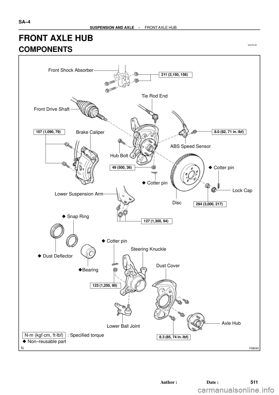
Front Shock Absorber
Tie Rod End
Front Drive Shaft
Brake Caliper
ABS Speed Sensor
Lower Suspension ArmLock Cap
� Snap Ring
� Dust DeflectorSteering Knuckle
Dust Cover
�Bearing
Lower Ball JointAxle Hub � Cotter pin� Cotter pin� Cotter pin Hub Bolt
Disc
N´m (kgf´cm, ft´lbf) : Specified torque
� Non±reusable part
127 (1,300, 94)
107 (1,090, 79)
49 (500, 36)
8.3 (85, 74 in.´lbf)
123 (1,250, 90)
211 (2,150, 156)
294 (3,000, 217)
8.0 (82, 71 in.´lbf)
SA±4
± SUSPENSION AND AXLEFRONT AXLE HUB
511 Author�: Date�:
FRONT AXLE HUB
COMPONENTS
Page 3633 of 4592
SA08P±02
F03274
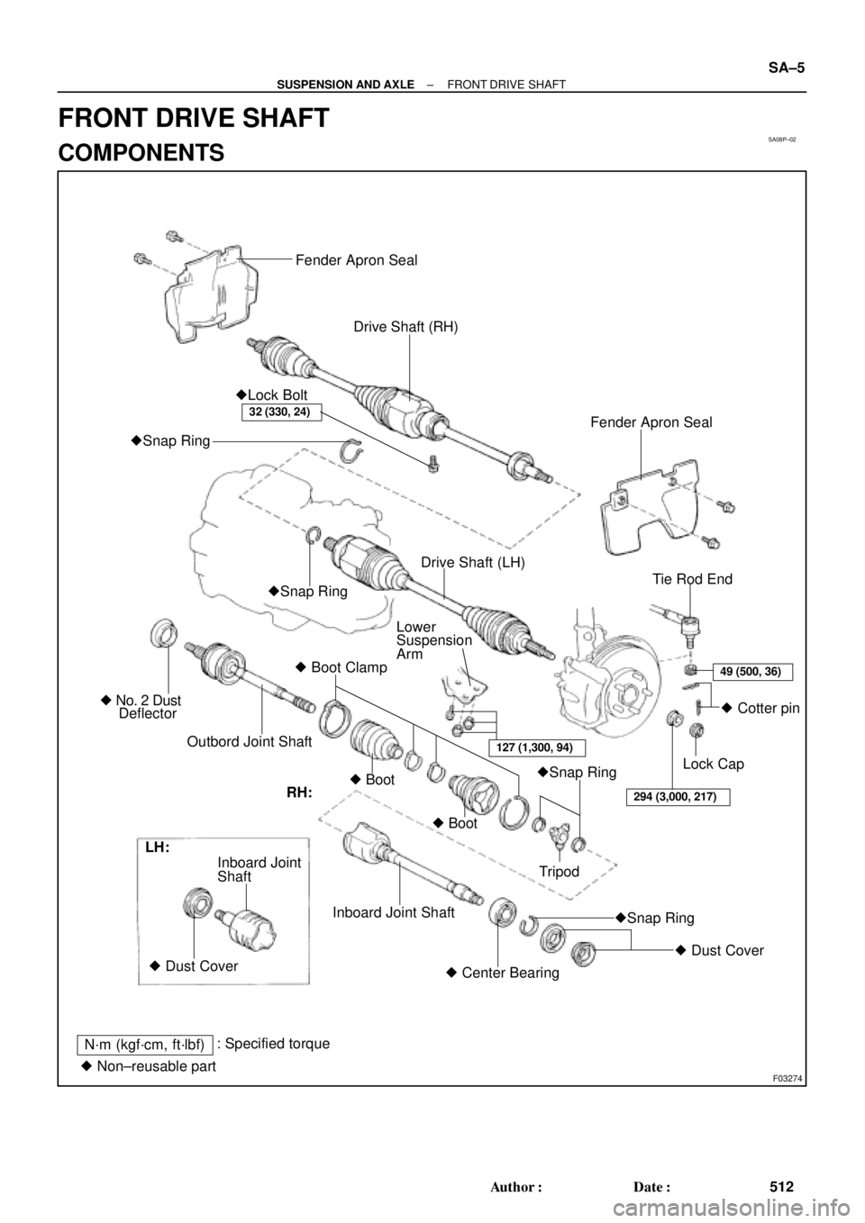
Fender Apron Seal
Drive Shaft (RH)
Fender Apron Seal �Lock Bolt
�Snap Ring
Tie Rod End
Lower
Suspension
Arm
� Boot Clamp
Outbord Joint Shaft � No. 2 Dust
Deflector�Snap RingDrive Shaft (LH)
�Snap Ring
�Snap Ring � Boot
� Boot� Cotter pin
Lock Cap
Tripod
� Dust Cover
� Center Bearing Inboard Joint Shaft Shaft Inboard Joint
� Dust Cover LH:
N´m (kgf´cm, ft´lbf): Specified torque
� Non±reusable part
32 (330, 24)
49 (500, 36)
294 (3,000, 217)
127 (1,300, 94)
RH:
± SUSPENSION AND AXLEFRONT DRIVE SHAFT
SA±5
512 Author�: Date�:
FRONT DRIVE SHAFT
COMPONENTS
Page 3642 of 4592
 Install a new snap ring to the inboard joint shaft.
(b) Coat the gear oil")
SA1EC±02
SA±14
± SUSPENSION AND AXLEFRONT DRIVE SHAFT
INSTALLATION
1. LH drive shaft:
INSTALL DRIVE SHAFT TO TRANSAXLE
(a) Install a new snap ring to the inboard joint shaft.
(b) Coat the gear oil to the inboard joint shaft and differential case sliding surface.
(c) Set the snap ring with opening side facing downward.
(d) Using a brass bar and hammer, install the drive shaft.
NOTICE:
Be careful not to damage the dust cover of the drive shaft and oil seal lip of the transaxle.
HINT:
Whether the inboard joint shaft is in contact with the pinion shaft or not can be known from the sound or feel-
ing when driving it in.
(e) Check that there is 2 ± 3 mm (0.08 ± 0.12 in.) of play in the axial direction.
(f) Check that the drive shaft cannot be removed by hand.
2. RH drive shaft:
INSTALL DRIVE SHAFT TO TRANSAXLE
(a) Install the drive shaft.
NOTICE:
Be careful not to damage the dust cover of the drive shaft and oil seal lip of the transaxle.
(b) Using pliers, install a new snap ring.
(c) Install a new bearing lock bolt.
Torque: 32 N´m (330 kgf´cm, 24 ft´lbf)
3. CONNECT DRIVE SHAFT TO AXLE HUB
NOTICE:
Be careful not to damage the boot and ABS speed sensor rotor.
4. CONNECT LOWER SUSPENSION ARM TO LOWER BALL JOINT
Torque: 127 N´m (1,300 kgf´cm, 94 ft´lbf)
5. CONNECT TIE ROD END TO STEERING KNUCKLE
(a) Connect the tie rod end to the steering knuckle.
(b) Install the nut and a new cotter pin.
If the holes for the cotter pin are not aligned, tighten the nut further up to 60°.
Torque: 49 N´m (500 kgf´cm, 36 ft´lbf)
6. INSTALL DRIVE SHAFT LOCK NUT
(a) While applying brakes, install the nut.
Torque: 294 N´m (3,000 kgf´cm, 217 ft´lbf)
(b) Install the lock cap and a new cotter pin.
If the holes for the cotter pin are not aligned, tighten the nut further up to 60°.
7. FILL AND CHECK ATF (See page DI±133)
8. INSTALL FRONT FENDER APRON SEAL
9. INSTALL FRONT WHEEL
Torque: 103 N´m (1,050 kgf´cm, 76 ft´lbf)
10. CHECK FRONT WHEEL ALIGNMENT (See page SA±1)
11. CHECK ABS SPEED SENSOR SIGNAL (See page DI±177)
Page 3643 of 4592
SA07X±06
F08043
Suspension Support
Spring Bumper
Link Stabilizer Bar
Shock
Absorber
ABS Speed Sensor
Wire Harness ClampFront Drive Shaft with Coil SpringUpper SeatBearing
Lower
Insulator
Lower Suspension Arm Lower Suspension
Bushing StopperBrake CaliperInsulator UpperSpring Support No. 2Suspension
Shock Absorber
Coil Spring
Tie Rod End
� Dust
Deflector
� Cotter Pin
� Cotter Pin� Cotter
Pin
Lower Ball jointDisc
Lock Cap ABS Speed Sensor
N´m (kgf´cm, ft´lbf): Specified torque
� Non±reusable part�
80 (820, 59)49 (500, 36)
39 (400, 29)
211 (2,150, 156)
107 (1,090, 79)
29 (300, 22)
123 (1,250, 90)49 (500, 36)
8.0 (82, 71 in.´lbf)
294 (3,000, 217)
206 (2,100, 152)
206 (2,100, 152)
206 (2,100, 152)
127 (1,300, 94)
127 (1,300, 94)
± SUSPENSION AND AXLEFRONT LOWER BALL JOINT
SA±15
522 Author�: Date�:
FRONT LOWER BALL JOINT
COMPONENTS