Page 3644 of 4592
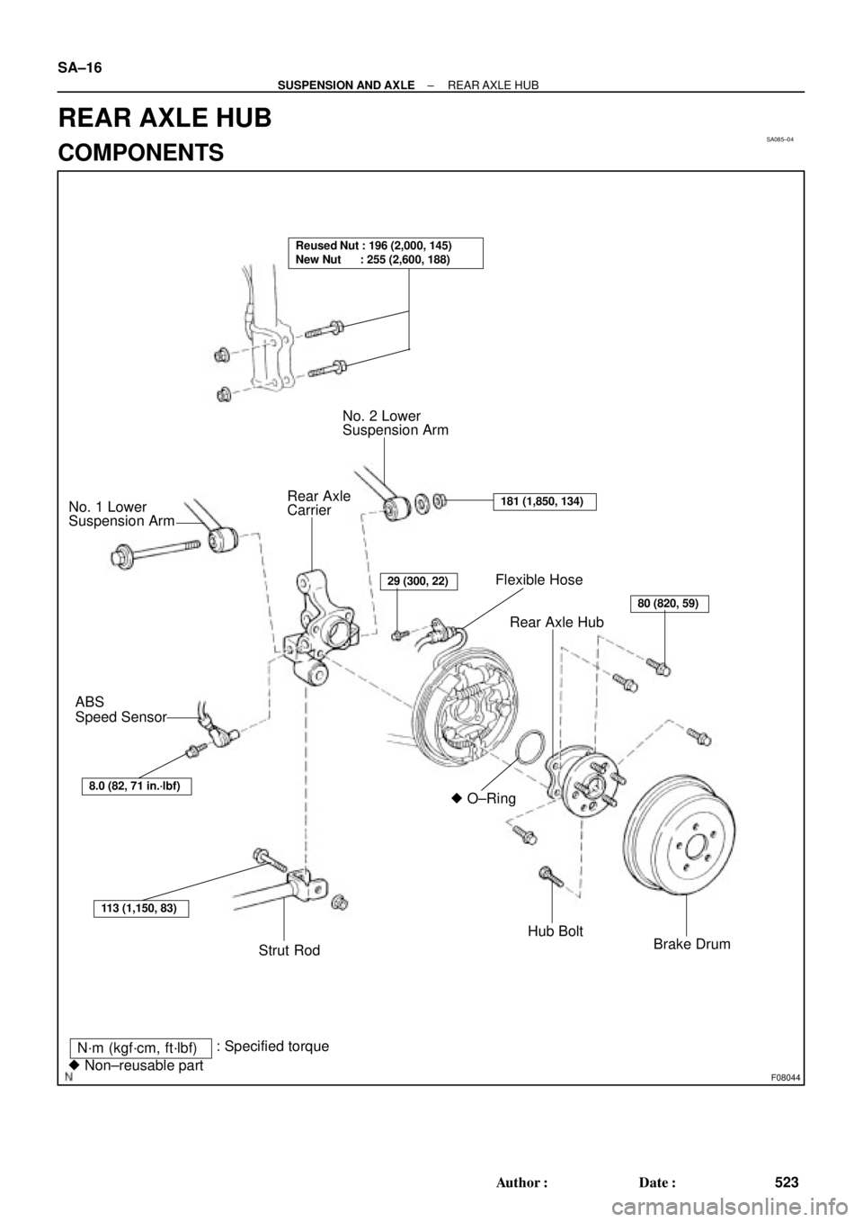
SA085±04
F08044
Flexible Hose
Rear Axle Hub
� O±Ring
Hub Bolt
Brake Drum No. 2 Lower
Suspension Arm
Rear Axle
Carrier No. 1 Lower
Suspension Arm
ABS
Speed Sensor
Strut Rod
N´m (kgf´cm, ft´lbf)
� Non±reusable part: Specified torque
Reused Nut : 196 (2,000, 145)
New Nut : 255 (2,600, 188)
8.0 (82, 71 in.´lbf)
113 (1,150, 83)
29 (300, 22)
80 (820, 59)
181 (1,850, 134)
SA±16
± SUSPENSION AND AXLEREAR AXLE HUB
523 Author�: Date�:
REAR AXLE HUB
COMPONENTS
Page 3645 of 4592
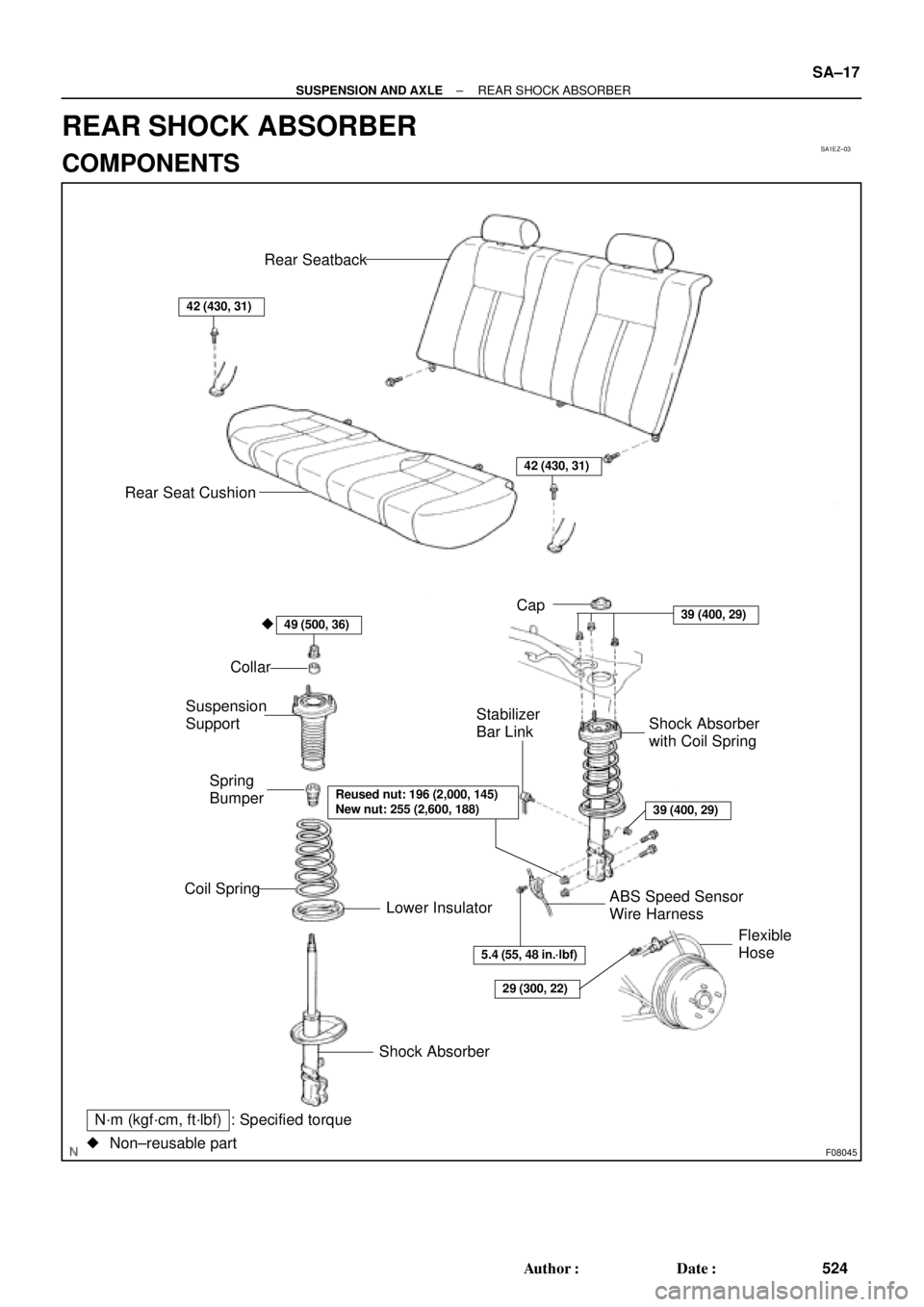
SA1EZ±03
F08045
: Specified torqueN´m (kgf´cm, ft´lbf)
Non±reusable part �Cap
Shock Absorber
42 (430, 31)
39 (400, 29)
Shock Absorber
with Coil Spring
39 (400, 29)
Stabilizer
Bar Link
42 (430, 31)
Rear Seatback
Rear Seat Cushion
Collar
Suspension
Support
Spring
Bumper
Coil Spring
Lower Insulator
�49 (500, 36)
Reused nut: 196 (2,000, 145)
New nut: 255 (2,600, 188)
ABS Speed Sensor
Wire Harness
5.4 (55, 48 in.´lbf)
29 (300, 22)
Flexible
Hose
± SUSPENSION AND AXLEREAR SHOCK ABSORBER
SA±17
524 Author�: Date�:
REAR SHOCK ABSORBER
COMPONENTS
Page 3647 of 4592
 Install the 3 nuts and shock absorber with the coil spring.
Torque: 39 N´m (400")
SA1F5±02
± SUSPENSION AND AXLEREAR SHOCK ABSORBER
SA±19
INSTALLATION
1. INSTALL SHOCK ABSORBER WITH COIL SPRING
(a) Install the 3 nuts and shock absorber with the coil spring.
Torque: 39 N´m (400 kgf´cm, 29 ft´lbf)
(b) Install the shock absorber with the coil spring, 2 bolts and nuts.
Torque:
Reused nut: 196 N´m (2,000 kgf´cm, 145 ft´lbf)
New nut: 255 N´m (2,600 kgf´cm, 188 ft´lbf)
HINT:
If reusing the 2 nuts, coat the threads of the 2 nuts with engine oil.
(c) Torque the nut in the center of the suspension support.
Torque: 49 N´m (500 kgf´cm, 36 ft´lbf)
HINT:
If the shock absorber has not been disassembled, it is not necessary to torque the nut.
(d) Install the cap.
2. CONNECT STABILIZER BAR LINK
Torque: 39 N´m (400 kgf´cm, 29 ft´lbf)
HINT:
If the ball joint turns together with the nut, use a hexagon (5 mm) wrench to hold the stud.
3. CONNECT FLEXIBLE HOSE AND ABS SPEED SENSOR WIRE HARNESS CLAMP
Torque:
Flexible hose: 29 N´m (300 kgf´cm, 22 ft´lbf)
ABS speed sensor wire harness: 5.4 N´m (55 kgf´cm, 48 in.´lbf)
4. INSTALL REAR WHEEL
Torque: 103 N´m (1,050 kgf´cm, 76 ft´lbf)
5. INSTALL REAR SEATBACK AND REAR SEAT CUSHION (See page BO±25)
6. CHECK REAR WHEEL ALIGNMENT (See Pub. No. RM654U on page SA±7)
Page 3648 of 4592
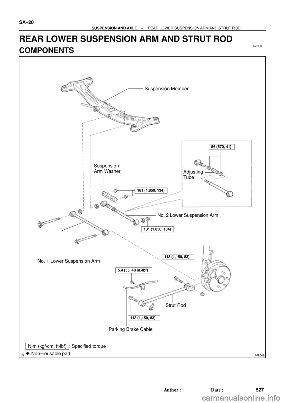
SA1F6±02
F08049
N´m (kgf´cm, ft´lbf) : Specified torque
Non±reusable part �
56 (570, 41)
181 (1,850, 134)
181 (1,850, 134)
113 (1,150, 83)
5.4 (55, 48 in.´lbf)
113 (1,150, 83)
Suspension Member
Adjusting
Tube
Suspension
Arm Washer
No. 2 Lower Suspension Arm
No. 1 Lower Suspension Arm
Parking Brake Cable
Strut Rod
SA±20
± SUSPENSION AND AXLEREAR LOWER SUSPENSION ARM AND STRUT ROD
527 Author�: Date�:
REAR LOWER SUSPENSION ARM AND STRUT ROD
COMPONENTS
Page 3650 of 4592

SA1JT±01
F08076
Rear
F08051
Rear
F08050
SA±22
± SUSPENSION AND AXLEREAR LOWER SUSPENSION ARM AND STRUT ROD
INSTALLATION
1. INSTALL NO. 1 LOWER SUSPENSION ARM
Install the No. 1 lower suspension arm, washer and 2 bolts.
HINT:
Face the paint mark to the rearward.
2. INSTALL NO. 2 LOWER SUSPENSION ARM
(a) Install the No. 2 lower suspension arm, washer and nut to
the axle carrier.
Torque: 181 N´m (1,850 kgf´cm, 134 ft´lbf)
HINT:
�Face the paint mark to the rearward.
�After stabilizing the suspension, torque the nut.
(b) Install the washer and connect the No. 2 lower suspen-
sion arm to the suspension member.
(c) Install the suspension arm washer and 2 nuts.
Torque: 181 N´m (1,850 kgf´cm, 134 ft´lbf)
HINT:
After stabilizing the suspension, torque the nut.
3. INSTALL STRUT ROD
Torque: 113 N´m (1,150 kgf´cm, 83 ft´lbf)
NOTICE:
Torque the bolt since the nut cannot be rotated.
HINT:
After stabilizing the suspension, torque the bolt.
4. CONNECT PARKING BRAKE CABLE
Torque: 5.4 N´m (55 kgf´cm, 48 in.´lbf)
5. INSTALL REAR WHEEL
Torque: 103 N´m (1,050 kgf´cm, 76 ft´lbf)
6. CHECK REAR WHEEL ALIGNMENT
(See Pub. No. RM654U on page SA±7)
Page 3651 of 4592
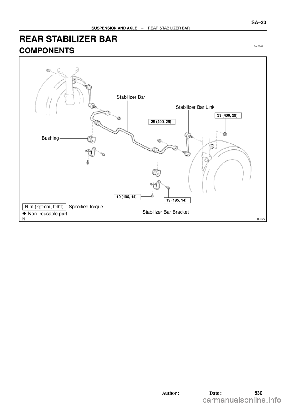
SA1FB±02
F08077
N´m (kgf´cm, ft´lbf) : Specified torque
Non±reusable part �
Bushing
Stabilizer Bar Bracket Stabilizer Bar
Stabilizer Bar Link
19 (195, 14)19 (195, 14)
39 (400, 29)
39 (400, 29)
± SUSPENSION AND AXLEREAR STABILIZER BAR
SA±23
530 Author�: Date�:
REAR STABILIZER BAR
COMPONENTS
Page 3653 of 4592
SA1FE±02
F08079
Bushing
Stopper
± SUSPENSION AND AXLEREAR STABILIZER BAR
SA±25
INSTALLATION
1. INSTALL STABILIZER BAR
2. INSTALL RIGHT AND LEFT BUSHINGS AND STABI-
LIZER BAR BRACKETS
Torque: 19 N´m (195 kgf´cm, 14 ft´lbf)
HINT:
Install the bushing to the outside of the bushing stopper on the
stabilizer bar.
3. INSTALL RIGHT AND LEFT STABILIZER BAR LINKS
Torque: 39 N´m (400 kgf´cm, 29 ft´lbf)
HINT:
If the ball joint turns together with the nut, use a hexagon (5 mm)
wrench to hold the stud.
Page 3695 of 4592
1997 CAMRY DOOR MIRROR INSTALLATIONPage 2 of 2
INSTALLATION PROCEDURES (Cont'd):
4. Tighten the three mirror mounting nuts A , B
and C for vehicles without a tweeter.
Torque: 5.5 N.m (56 kgf.cm, 49 in.lbf)
Connect the mirror wire.
5. Tighten the two mirror mounting nuts A and
B for vehicles with a tweeter.
Torque: 5.5 N.m (56 kgf.cm, 49 in.lbf)
Connect the mirror wire.
While lightly pulling the mirror wire
backward, install the tweeter and tighten
nut C.
Torque: 5.5 N.m (56 kgf.cm, 49 in.lbf)
NOTE:Check that the mirror wire is free
from the tweeter bracket.
6. Check the following items:
�There is no clearance between the door
mirror base and the door molding lip.
�The door frame molding lip is not tucked
under the mirror base.
7. Install the front door lower frame bracket
garnish.
8. Install the black cap onto the nut.
BC
A
B
A
C
Molding Lip
Mirror Base
Garnish
Cap

:
4. Tighten the three mirror mounting nuts A , B
and C for vehicles without a tweeter.
Torque: 5.5 N.m (56 kgf.cm, 49 in")