Page 3599 of 4592
SA07X±05
F06530
Suspension Support
Spring Bumper
Link Stabilizer Bar
Shock
Absorber
ABS Speed Sensor
Wire Harness ClampFront Drive Shaft with Coil SpringUpper Seat Bearing
Lower
Insulator
Lower Suspension Arm Lower Suspension
Bushing StopperBrake CaliperInsulator UpperSpring Support No. 2Suspension
Shock Absorber
Coil Spring
Tie Rod End
� Dust
Deflector
� Cotter Pin
� Cotter Pin� Cotter
Pin
Lower Ball jointDisc
Lock Cap ABS Speed Sensor
N´m (kgf´cm, ft´lbf): Specified torque
� Non±reusable part�
80 (820, 59)49 (500, 36)
39 (400, 29)
211 (2,150, 156)
107 (1,090, 79)
29 (300, 22)
123 (1,250, 90)49 (500, 36)
8.0 (82, 71 in.´lbf)
294 (3,000, 217)
206 (2,100, 152)
206 (2,100, 152)
206 (2,100, 152)
127 (1,300, 94)
127 (1,300, 94)
± SUSPENSION AND AXLEFRONT LOWER BALL JOINT
SA±43
1994 Author�: Date�:
FRONT LOWER BALL JOINT
COMPONENTS
Page 3601 of 4592
SA07Z±01
N00208
± SUSPENSION AND AXLEFRONT LOWER BALL JOINT
SA±45
1996 Author�: Date�:
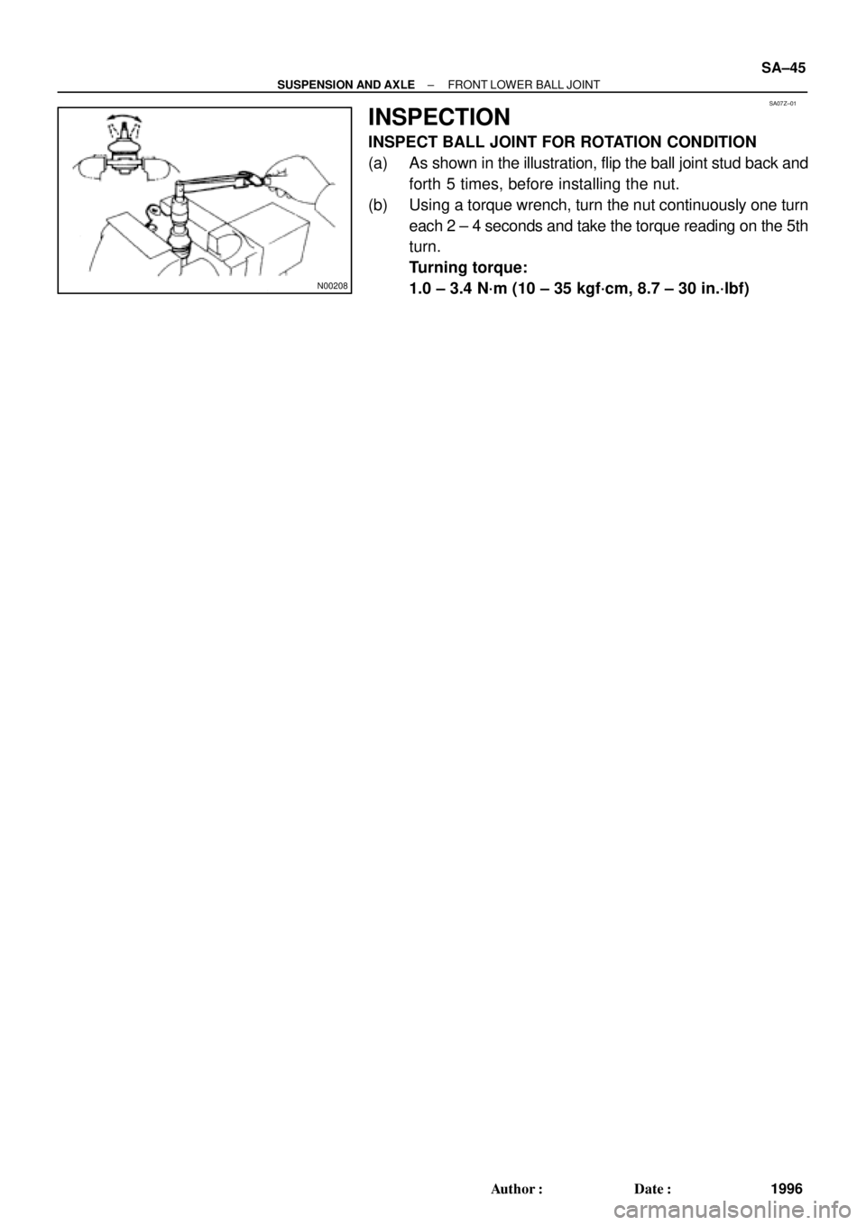
INSPECTION
INSPECT BALL JOINT FOR ROTATION CONDITION
(a) As shown in the illustration, flip the ball joint stud back and
forth 5 times, before installing the nut.
(b) Using a torque wrench, turn the nut continuously one turn
each 2 ± 4 seconds and take the torque reading on the 5th
turn.
Turning torque:
1.0 ± 3.4 N´m (10 ± 35 kgf´cm, 8.7 ± 30 in.´lbf)
Page 3602 of 4592
SA080±01
R08850
R08861
SST
SST SA±46
± SUSPENSION AND AXLEFRONT LOWER BALL JOINT
1997 Author�: Date�:
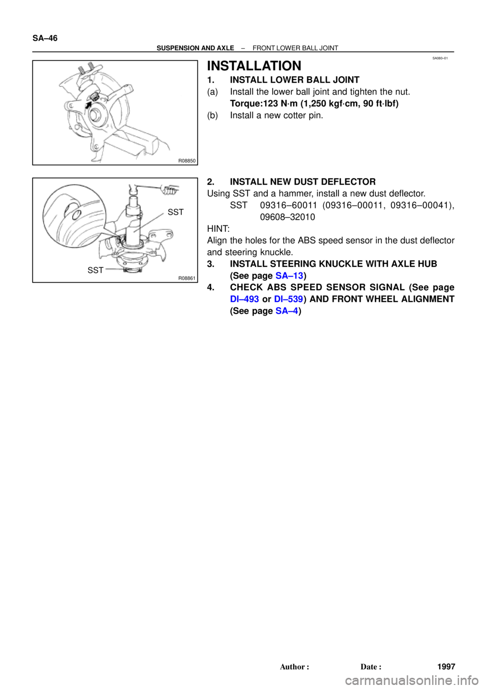
INSTALLATION
1. INSTALL LOWER BALL JOINT
(a) Install the lower ball joint and tighten the nut.
Torque:123 N´m (1,250 kgf´cm, 90 ft´lbf)
(b) Install a new cotter pin.
2. INSTALL NEW DUST DEFLECTOR
Using SST and a hammer, install a new dust deflector.
SST 09316±60011 (09316±00011, 09316±00041),
09608±32010
HINT:
Align the holes for the ABS speed sensor in the dust deflector
and steering knuckle.
3. INSTALL STEERING KNUCKLE WITH AXLE HUB
(See page SA±13)
4. CHECK ABS SPEED SENSOR SIGNAL (See page
DI±493 or DI±539) AND FRONT WHEEL ALIGNMENT
(See page SA±4)
Page 3603 of 4592
SA081±01
W03207
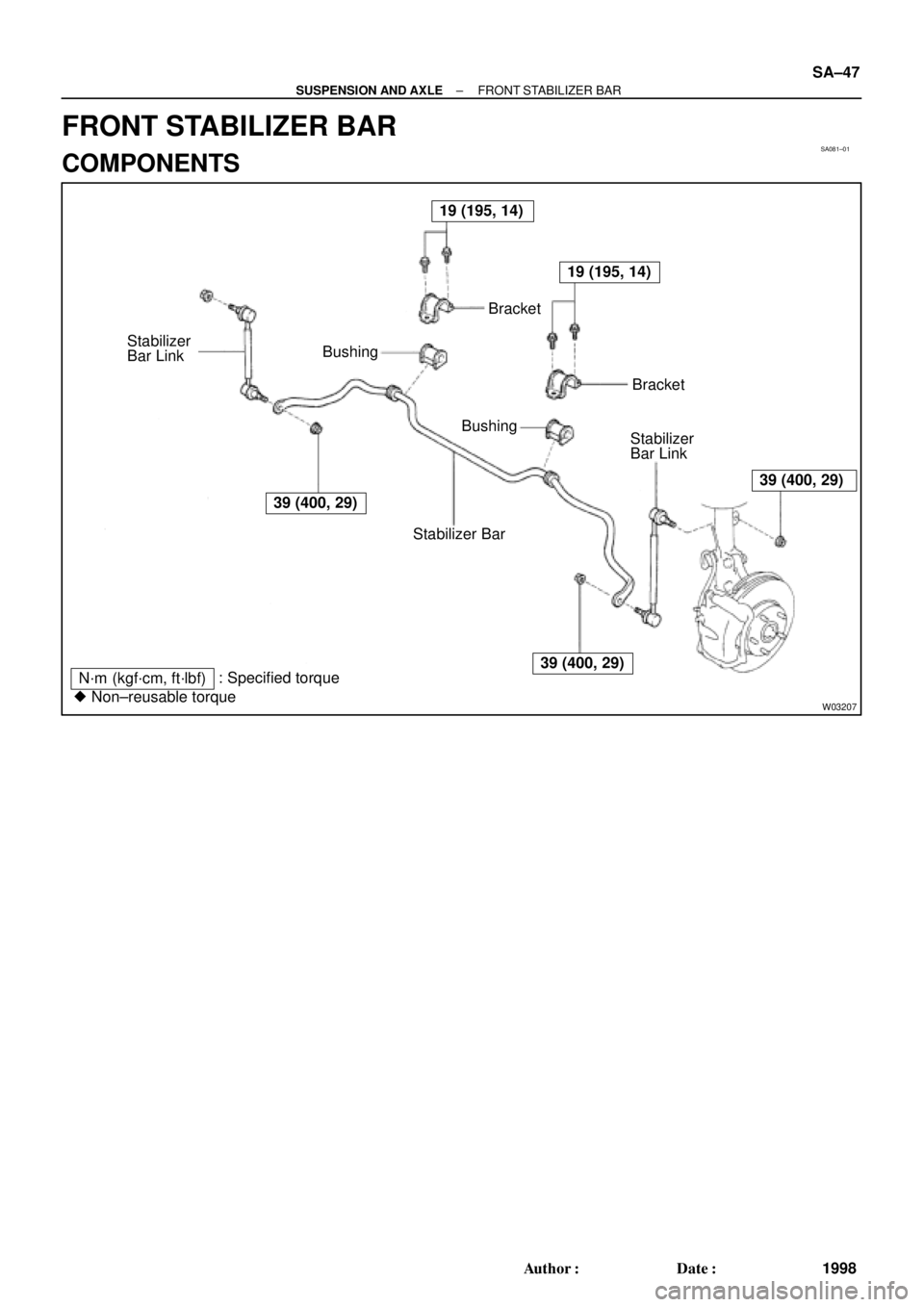
19 (195, 14)
39 (400, 29)
19 (195, 14)
39 (400, 29)
39 (400, 29)
N´m (kgf´cm, ft´lbf): Specified torque
� Non±reusable torqueStabilizer BarBracket BushingBracket
Stabilizer
Bar Link
Bushing
Stabilizer
Bar Link
± SUSPENSION AND AXLEFRONT STABILIZER BAR
SA±47
1998 Author�: Date�:
FRONT STABILIZER BAR
COMPONENTS
Page 3604 of 4592
SA082±01
W03208
W03209
SA±48
± SUSPENSION AND AXLEFRONT STABILIZER BAR
1999 Author�: Date�:
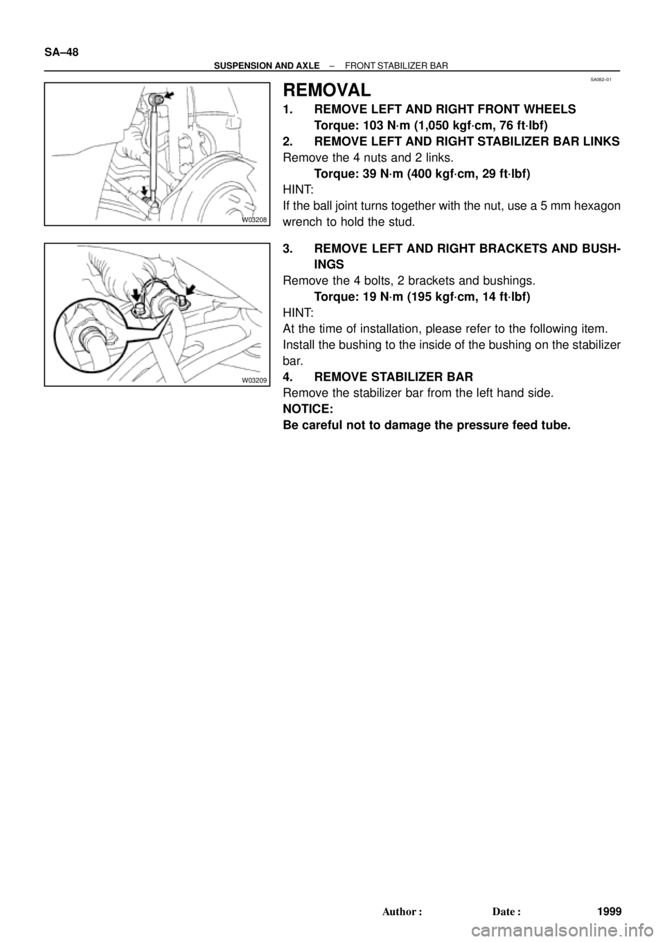
REMOVAL
1. REMOVE LEFT AND RIGHT FRONT WHEELS
Torque: 103 N´m (1,050 kgf´cm, 76 ft´lbf)
2. REMOVE LEFT AND RIGHT STABILIZER BAR LINKS
Remove the 4 nuts and 2 links.
Torque: 39 N´m (400 kgf´cm, 29 ft´lbf)
HINT:
If the ball joint turns together with the nut, use a 5 mm hexagon
wrench to hold the stud.
3. REMOVE LEFT AND RIGHT BRACKETS AND BUSH-
INGS
Remove the 4 bolts, 2 brackets and bushings.
Torque: 19 N´m (195 kgf´cm, 14 ft´lbf)
HINT:
At the time of installation, please refer to the following item.
Install the bushing to the inside of the bushing on the stabilizer
bar.
4. REMOVE STABILIZER BAR
Remove the stabilizer bar from the left hand side.
NOTICE:
Be careful not to damage the pressure feed tube.
Page 3605 of 4592
SA083±01
Z00340
± SUSPENSION AND AXLEFRONT STABILIZER BAR
SA±49
2000 Author�: Date�:
INSPECTION
INSPECT STABILIZER BAR LINK BALL JOINT FOR ROTA-
TION CONDITION
(a) As shown in the illustration, flip the ball joint stud back and
forth 5 times, before installing the nut.
(b) Using a torque wrench, turn the nut continuously one turn
each 2 ± 4 seconds and take the torque reading on the 5th
turn.
Turning torque:
0.05 ± 1.0 N´m (0.5 ± 10 kgf´cm, 0.4 ± 8.7 in.´lbf)
Page 3607 of 4592
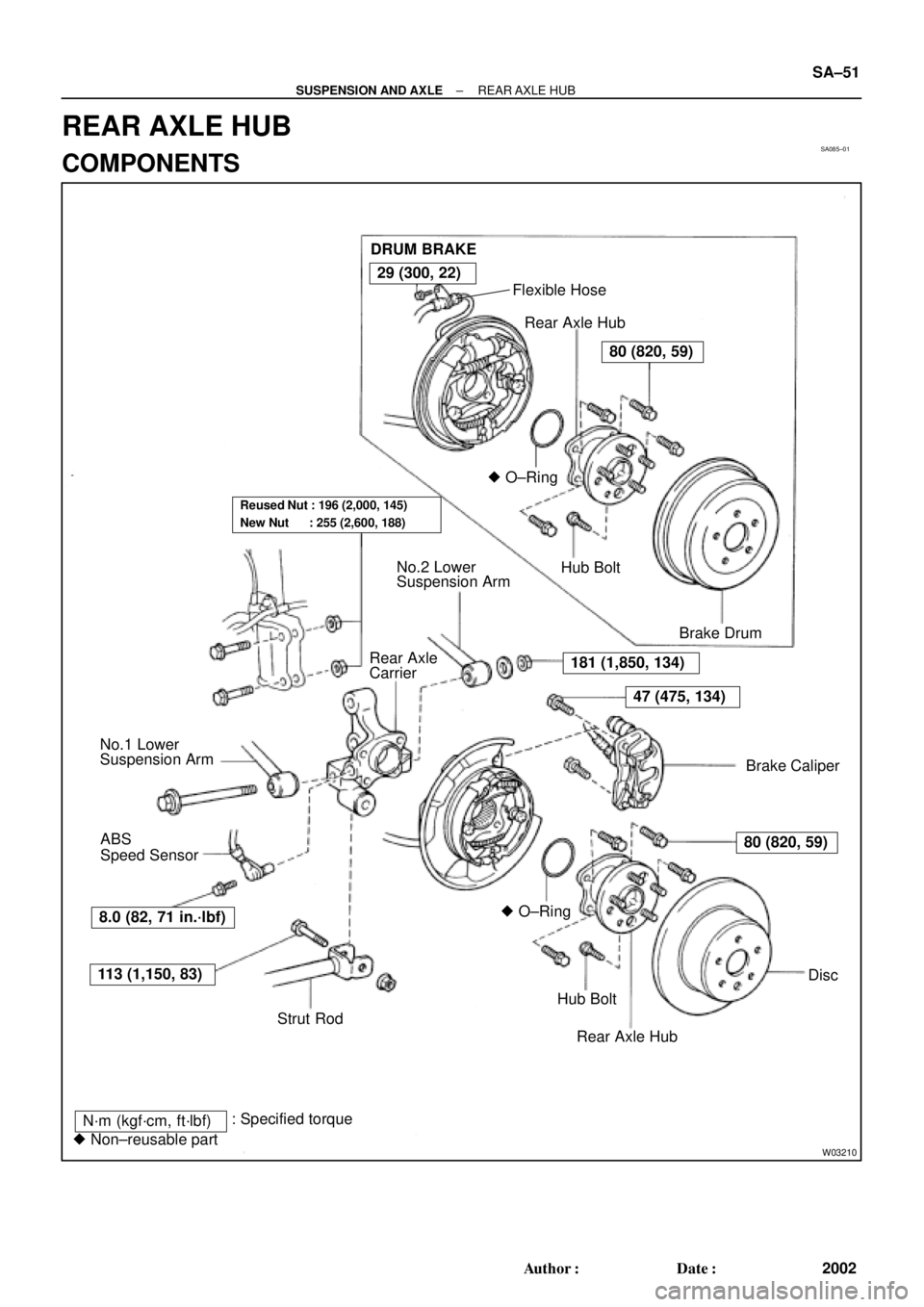
SA085±01
W03210
DRUM BRAKE
Flexible Hose
Rear Axle Hub
� O±Ring
Hub Bolt
Brake Drum
Brake Caliper No.2 Lower
Suspension Arm
Rear Axle
Carrier
No.1 Lower
Suspension Arm
� O±Ring
Hub Bolt
Rear Axle HubDisc ABS
Speed Sensor
Strut Rod
N´m (kgf´cm, ft´lbf)
� Non±reusable part: Specified torque
181 (1,850, 134)
47 (475, 134)
80 (820, 59)
113 (1,150, 83)
29 (300, 22)
80 (820, 59)
Reused Nut : 196 (2,000, 145)
New Nut : 255 (2,600, 188)
8.0 (82, 71 in.´lbf)
± SUSPENSION AND AXLEREAR AXLE HUB
SA±51
2002 Author�: Date�:
REAR AXLE HUB
COMPONENTS
Page 3608 of 4592

2. w/ DISC BRAKE:
REMOVE BRAKE CALIPE")
SA086±01
R10948
Z00206
SA±52
± SUSPENSION AND AXLEREAR AXLE HUB
2003 Author�: Date�:
REMOVAL
1. REMOVE REAR WHEEL
Torque: 103 N´m (1,050 kgf´cm, 76 ft´lbf)
2. w/ DISC BRAKE:
REMOVE BRAKE CALIPER AND DISC
(a) Remove the brake caliper and disc.
Torque: 47 N´m (475 kgf´cm, 34 ft´lbf)
(b) Support the brake caliper securely.
3. w/ DRUM BRAKE:
REMOVE BRAKE DRUM
4. CHECK BEARING BACKLASH AND AXLE HUB DEVI-
ATION
(a) Using a dial indicator near the center of the axle hub and
check the backlash in the bearing shaft direction.
Maximum: 0.05 mm (0.0020 in.)
If the backlash exceeds the maximum, replace the axle hub with
the bearing.
(b) Using a dial indicator, check the deviation at the surface
of the axle hub outside the hub bolt.
Maximum: 0.07 mm (0.0028 in.)
If the deviation exceeds the maximum, replace the axle hub
with the bearing.
5. REMOVE REAR AXLE HUB
(a) Remove the 4 bolts and rear axle hub.
Torque: 80 N´m (820 kgf´cm, 59 ft´lbf)
(b) Remove the O±ring.
HINT:
At the time of installation, coat a new O±ring with MP grease.