Page 3525 of 4592
W03365
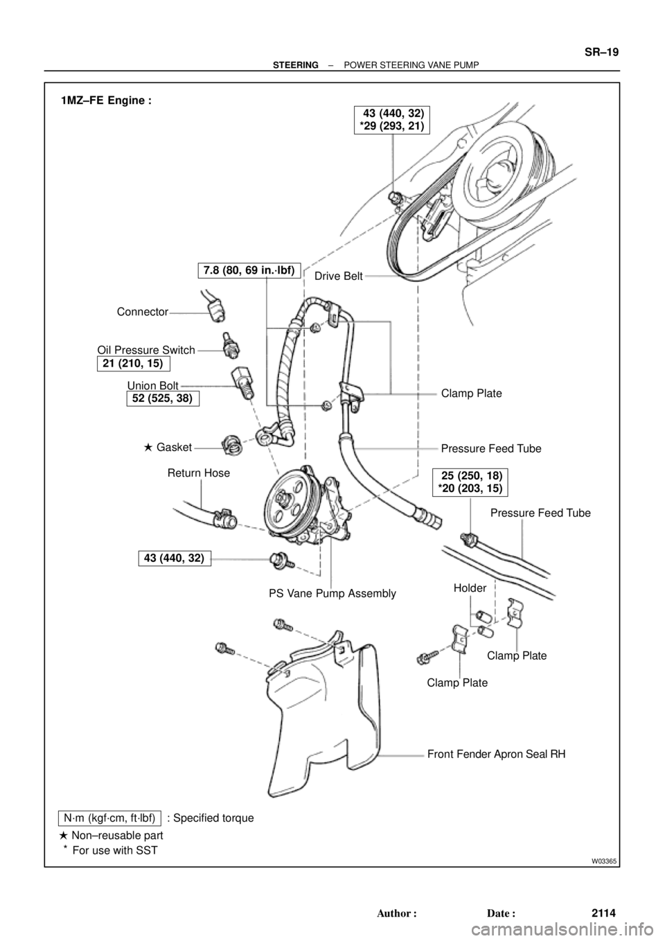
Drive Belt
Clamp Plate
Pressure Feed Tube
Pressure Feed Tube
Clamp Plate
Clamp Plate
Front Fender Apron Seal RH
N´m (kgf´cm, ft´lbf)
� Non±reusable part
For use with SST: Specified torquePS Vane Pump Assembly Return Hose � Gasket Union Bolt Connector
Oil Pressure Switch
43 (440, 32)
52 (525, 38)
21 (210, 15)
7.8 (80, 69 in.´lbf)
25 (250, 18)
*20 (203, 15)
43 (440, 32)
*29 (293, 21) 1MZ±FE Engine :
Holder
*
± STEERINGPOWER STEERING VANE PUMP
SR±19
2114 Author�: Date�:
Page 3526 of 4592
W03349
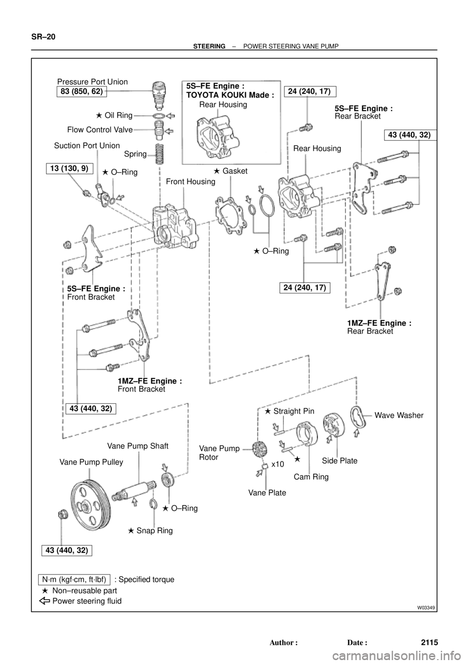
Pressure Port Union
� Oil Ring
Flow Control Valve
Suction Port Union
Spring
� O±Ring
Front Housing� Gasket Rear Housing
Rear Bracket
Rear Housing
� O±Ring
Rear Bracket
Wave Washer
�
Cam Ring � Straight Pin
Vane Plate Rotor
Side Plate Vane Pump
x10
� O±Ring
� Snap Ring
N´m (kgf´cm, ft´lbf)
Non±reusable part
Power steering fluid: Specified torque Vane Pump Shaft
Vane Pump PulleyFront Bracket Front Bracket
�
5S±FE Engine :
TOYOTA KOUKI Made :24 (240, 17)
43 (440, 32)
24 (240, 17)
83 (850, 62)
13 (130, 9)
5S±FE Engine :5S±FE Engine :
1MZ±FE Engine :1MZ±FE Engine :
43 (440, 32)
43 (440, 32) SR±20
± STEERINGPOWER STEERING VANE PUMP
2115 Author�: Date�:
Page 3528 of 4592

SR06P±01
W03338
Example 5S±FE Engine :
W03339
Example 5S±FE Engine :
SST SR±22
± STEERINGPOWER STEERING VANE PUMP
2117 Author�: Date�:
DISASSEMBLY
NOTICE:
When using a vise, do not overtighten it.
1. MEASURE PS VANE PUMP ROTATING TORQUE
(a) Check that the pump rotates smoothly without abnormal
noise.
(b) Using a torque wrench, check the pump rotating torque.
5S±FE and 1MZ±FE Engines:
Rotating torque:
0.3 N´m (2.8 kgf´cm, 2.4 in.´lbf) or less
2. REMOVE VANE PUMP PULLEY
Using SST, to stop the pulley rotating, remove the nut.
SST 09960±10010 (09962±01000, 09963±01000)
3. REMOVE FRONT AND REAR BRACKETS
Remove the 3 bolts and 2 nuts.
4. REMOVE SUCTION PORT UNION
(a) Remove the bolt.
(b) Remove the O±ring from the union.
5. REMOVE PRESSURE PORT UNION, FLOW CONTROL
VALVE AND SPRING
Remove the O±ring from the union.
6. REMOVE REAR HOUSING
(a) Remove the 4 bolts.
(b) Remove the 2 O±rings from the housing.
7. REMOVE WAVE WASHER
8. REMOVE SIDE PLATE
9. REMOVE GASKET
10. REMOVE CAM RING, 10 VANE PLATES AND VANE
PUMP ROTOR
Using a screwdriver, remove the snap ring from the vane pump
shaft.
NOTICE:
Take care not to drop the plate.
11. REMOVE VANE PUMP SHAFT
12. REMOVE STRAIGHT PINS
Remove the 2 pins from the front housing.
Page 3532 of 4592

SR06R±01
R13458
Inscribed Mark
R01149
Round End
R11292
SR±26
± STEERINGPOWER STEERING VANE PUMP
2121 Author�: Date�:
REASSEMBLY
NOTICE:
When using a vise, do not overtighten it.
1. COAT WITH POWER STEERING FLUID
(See page SR±18)
2. INSTALL VANE PUMP SHAFT
3. INSTALL STRAIGHT PINS
Using a plastic hammer, tap in 2 new pins.
NOTICE:
Be careful not to damage the pins.
4. INSTALL CAM RING
Align the holes of the ring and 2 straight pins, and install the ring
with the inscribed mark facing outward.
5. INSTALL VANE PUMP ROTOR
(a) Install the rotor with the inscribed mark facing outward.
(b) Install a new snap ring to the vane pump shaft.
6. INSTALL VANE PLATES
Install the 10 plates with the round end facing outward.
7. INSTALL GASKET
Install a new gasket.
8. INSTALL SIDE PLATE
Align the holes of the plate and 2 straight pins.
9. INSTALL WAVE WASHER
Install the washer so that its protrusions fit into the slots in the
side plate.
10. INSTALL REAR HOUSING
(a) Coat 2 new O±rings with power steering fluid and install
them to the housing.
(b) Torque the 4 bolts.
5S±FE and 1MZ±FE Engines:
Torque: 24 N´m (240 kgf´cm, 17 ft´lbf)
Page 3533 of 4592
W03339
Example 5S±FE Engine :
SST
± STEERINGPOWER STEERING VANE PUMP
SR±27
2122 Author�: Date�:
11. INSTALL SPRING, FLOW CONTROL VALVE AND
PRESSURE PORT UNION
(a) Install the valve facing the correct direction.
(See page SR±18)
(b) Coat a new O±ring with power steering fluid and install it
to the union.
(c) Torque the union.
5S±FE and 1MZ±FE Engines:
Torque: 83 N´m (850 kgf´cm, 62 ft´lbf)
12. INSTALL SUCTION PORT UNION
(a) Coat a new O±ring with power steering fluid and install it
to the union.
(b) Torque the bolt.
5S±FE and 1MZ±FE Engines:
Torque: 13 N´m (130 kgf´cm, 9 ft´lbf)
13. INSTALL FRONT AND REAR BRACKETS
Torque the 3 bolts and 2 nuts.
5S±FE and 1MZ±FE Engines:
Torque: 43 N´m (440 kgf´cm, 32 ft´lbf)
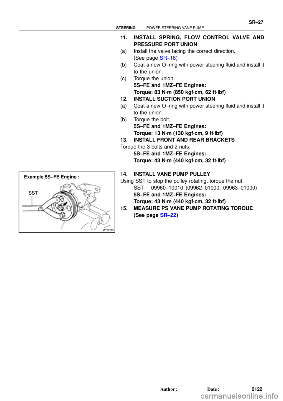
14. INSTALL VANE PUMP PULLEY
Using SST to stop the pulley rotating, torque the nut.
SST 09960±10010 (09962±01000, 09963±01000)
5S±FE and 1MZ±FE Engines:
Torque: 43 N´m (440 kgf´cm, 32 ft´lbf)
15. MEASURE PS VANE PUMP ROTATING TORQUE
(See page SR±22)
Page 3534 of 4592
SR06S±01
W03361
5S±FE Engine :
1MZ±FE Engine :Pressure Feed Tube
Stopper
Pressure
Feed
StopperTube
W03360
Example 5S±FE Engine :
A
B
W03542
5S±FE Engine :
SST
Fulcrum
Length SR±28
± STEERINGPOWER STEERING VANE PUMP
2123 Author�: Date�:
INSTALLATION
1. INSTALL PRESSURE FEED TUBE
(a) Torque the union bolt with a new gasket.
HINT:
Make sure the stopper of the tube is touching the front bracket,
as shown, then torque the union bolt.
5S±FE and 1MZ±FE Engines:
Torque: 52 N´m (525 kgf´cm, 38 ft´lbf)
(b) Install the oil pressure switch to the union bolt.
5S±FE and 1MZ±FE Engines:
Torque: 21 N´m (210 kgf´cm, 15 ft´lbf)
2. INSTALL PS VANE PUMP ASSEMBLY WITH PRESS-
ER FEED TUBE
Temporarily tighten the 2 (A and B) bolts.
3. INSTALL DRIVE BELT
(a) Adjust drive belt tension.
(See page SR±3)
(b) 5S±FE Engine:
Using SST, torque the A bolt.
SST 09249±63010
Torque: 29 N´m (293 kgf´cm, 21 ft´lbf)
HINT:
Use a torque wrench with a fulcrum length of 300 mm (11.81
in.).
Page 3535 of 4592

W03543
1MZ±FE Engine :
Engine Wire Clamp
Fulcrum
Length
SST
W04221
5S±FE Engine :
1MZ±FE Engine :Fulcrum
Length
SST Pressure
Feed Tube
Fulcrum
LengthSST
± STEERINGPOWER STEERING VANE PUMP
SR±29
2124 Author�: Date�:
(c) 1MZ±FE Engine:
Using SST, torque the A bolt.
SST 09249±63010
Torque: 29 N´m (293 kgf´cm, 21 ft´lbf)
HINT:
�Use a torque wrench with a fulcrum length of 300 mm
(11.81 in.).
�Disconnect the clamp with engine wire.
(d) Torque the B bolt.
5S±FE and 1MZ±FE Engines:
Torque: 43 N´m (440 kgf´cm, 32 ft´lbf)
(e) Connect the connector to the oil pressure switch.
NOTICE:
Be careful for oil on the connector.
4. CONNECT PRESSURE FEED TUBE
(a) Using SST, connect the tube.
SST 09631±22020
5S±FE Engine:
Torque: 32 N´m (326 kgf´cm, 24 ft´lbf)
1MZ±FE Engine:
Torque: 20 N´m (203 kgf´cm, 15 ft´lbf)
HINT:
�Use a torque wrench with a fulcrum length of 300 mm
(11.81 in.).
�This torque value is effective in case that SST is parallel
to a torque wrench.
(b) 5S±FE Engine:
Install the clamp to the tube.
(c) 5S±FE Engine:
Install the 2 clamp plates and 2 holders to the tube.
(d) 5S±FE Engine:
Install the clamp plate set bolt.
(e) 5S±FE Engine:
Install the clamp plate set nut.
Torque: 10 N´m (100 kgf´cm, 7 ft´lbf)
(f) 1MZ±FE Engine:
Install the 2 clamp plates and 2 holders to the tube.
(g) 1MZ±FE Engine:
Tighten the bolt.
(h) 1MZ±FE Engine:
Install the 2 clamp plate set nuts.
Torque: 7.8 N´m (80 kgf´cm, 69 in.´lbf)
5. CONNECT RETURN HOSE
Page 3537 of 4592
SR06T±01
W03350
Stabilizer Bar
No.1 Fuel Tube Protector
Intermediate Shaft
Assembly
Pressure Feed Tube
PS Gear Assembly
N´m (kgf´cm, ft´lbf) : Specified torque
Non±reusable part
For use with SSTClamp Plate
Return
Tube
�
*� Cotter pin �
19 (195, 14)
19 (195, 14)
25 (250, 18)
*32 (326, 24)
181 (1,850, 134)
49 (500, 36)
49 (500, 36)
35 (360, 26)
181 (1,850, 134)
10 (100, 7)
± STEERINGPOWER STEERING GEAR
SR±31
2126 Author�: Date�:
POWER STEERING GEAR
COMPONENTS

 : Specified torque
Non±reusable part
For use with SSTC")