Page 3417 of 4592
INJECTOR
SF±29
1528 Author�: Date�:
(g) Apply a light coat of spindle oil or gasoline on the place
where a intake manifold touc")
B01021
S04728
Rotate
Outward
B01020
S06525
Align
S05351
± SFI (1MZ±FE)INJECTOR
SF±29
1528 Author�: Date�:
(g) Apply a light coat of spindle oil or gasoline on the place
where a intake manifold touches an O±ring of the injector.
(h) Place the delivery pipes and fuel pipe together with the 6
injectors in position on the intake manifold.
(i) Temporarily install the 4 bolts holding the delivery pipes
to the intake manifold.
(j) Temporarily install the bolt holding the No.1 fuel pipe to
the intake manifold.
(k) Check that the injectors rotate smoothly.
HINT:
If injectors do not rotate smoothly, the probable cause is incor-
rect installation of O±rings. Replace the O±rings.
(l) Position the injector connector outward.
(m) Tighten the 4 bolts holding the delivery pipes to the intake
manifold.
Torque: 10 N´m (100 kgf´cm, 7 ft´lbf)
(n) Tighten the bolt holding the No.1 fuel pipe to the intake
manifold.
Torque: 19.5 N´m (200 kgf´cm, 14 ft´lbf)
2. CONNECT NO.1 FUEL PIPE
(a) Align the alignment marks (white paint) on the No.1 fuel
pipe.
(b) Connect the No.1 fuel pipe (fuel tube connector) to the
fuel filter.
CAUTION:
Perform connecting operations of the fuel tube connector
(quick type) after observing the precaution.
(See page SF±1)
Page 3419 of 4592

Before installing the heated oxygen sensor,
twist the sensor wire counterclockwise
3 and 1/2 turns. HINT:
After installing the heated oxygen sen")
SF07N±03
B06469
Heated Oxygen Sensor (Bank 1 Sensor 2)
Before installing the heated oxygen sensor,
twist the sensor wire counterclockwise
3 and 1/2 turns. HINT:
After installing the heated oxygen sensor,
check that the sensor wire is not twisted,
if it is twisted, remove the heated oxygen
sensor and reinstall it. �
Location of Fuel Tank Cushion
No.1 Fuel Tank
Protector
Fuel Tank Vent
Tube Set Plate
Fuel Pump
Fuel Outlet Tube
Fuel Inlet Pipe Fuel Inlet Pipe ShieldFuel Tank Cap
Fuel Inlet Pipe Protector
Heated Oxygen Sensor
(Bank 1 Sensor 2)Heat Insulator
Fuel Tank Band
Center Exhaust Pipe � Gasket� Gasket � Gasket
� Non±reusable part
N´m (kgf´cm, ft´lbf): Specified torque
39 (400, 29)
44 (450, 33)
56 (570, 41)
56 (570, 41)
x 8
�
� Gasket
Fuel TankFuel Inlet Hose
Charcoal
Canister
EVAP Line Hose
Vent Line Hose
± SFI (1MZ±FE)FUEL TANK AND LINE
SF±31
1530 Author�: Date�:
FUEL TANK AND LINE
COMPONENTS
CAUTION:
�Always use new gaskets when replacing the fuel tank or component parts.
�Apply the proper torque to all parts tightened.
Page 3426 of 4592
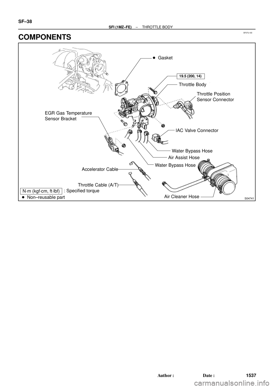
SF07U±03
S04741
EGR Gas Temperature
Sensor Bracket� Gasket
Throttle Body
Throttle Position
Sensor Connector
IAC Valve Connector
Water Bypass Hose
Air Assist Hose
Water Bypass Hose
Air Cleaner Hose Accelerator Cable
Throttle Cable (A/T)
N´m (kgf´cm, ft´lbf)
� Non±reusable part: Specified torque
19.5 (200, 14)
SF±38
± SFI (1MZ±FE)THROTTLE BODY
1537 Author�: Date�:
COMPONENTS
Page 3427 of 4592
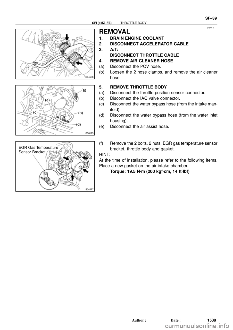
SF07V±03
S04506
S06123
(a)
(b)
(d) (e)
(c)
S04527
EGR Gas Temperature
Sensor Bracket
± SFI (1MZ±FE)THROTTLE BODY
SF±39
1538 Author�: Date�:
REMOVAL
1. DRAIN ENGINE COOLANT
2. DISCONNECT ACCELERATOR CABLE
3. A/T:
DISCONNECT THROTTLE CABLE
4. REMOVE AIR CLEANER HOSE
(a) Disconnect the PCV hose.
(b) Loosen the 2 hose clamps, and remove the air cleaner
hose.
5. REMOVE THROTTLE BODY
(a) Disconnect the throttle position sensor connector.
(b) Disconnect the IAC valve connector.
(c) Disconnect the water bypass hose (from the intake man-
ifold).
(d) Disconnect the water bypass hose (from the water inlet
housing).
(e) Disconnect the air assist hose.
(f) Remove the 2 bolts, 2 nuts, EGR gas temperature sensor
bracket, throttle body and gasket.
HINT:
At the time of installation, please refer to the following items.
Place a new gasket on the air intake chamber.
Torque: 19.5 N´m (200 kgf´cm, 14 ft´lbf)
Page 3432 of 4592
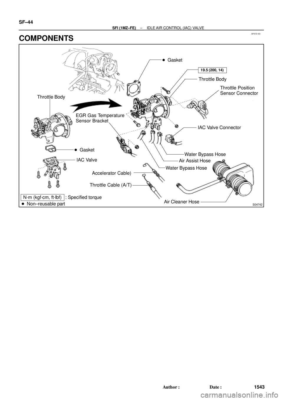
SF07Z±03
S04742
� Gasket
Throttle Body
Throttle Position
Sensor Connector
Water Bypass Hose
Air Cleaner HoseAir Assist Hose
Accelerator Cable)
Throttle Cable (A/T) EGR Gas Temperature
Sensor Bracket
N´m (kgf´cm, ft´lbf) : Specified torque
� Non±reusable partWater Bypass HoseIAC Valve Connector
19.5 (200, 14)
� Gasket Throttle Body
IAC Valve
SF±44
± SFI (1MZ±FE)IDLE AIR CONTROL (IAC) VALVE
1543 Author�: Date�:
COMPONENTS
Page 3437 of 4592
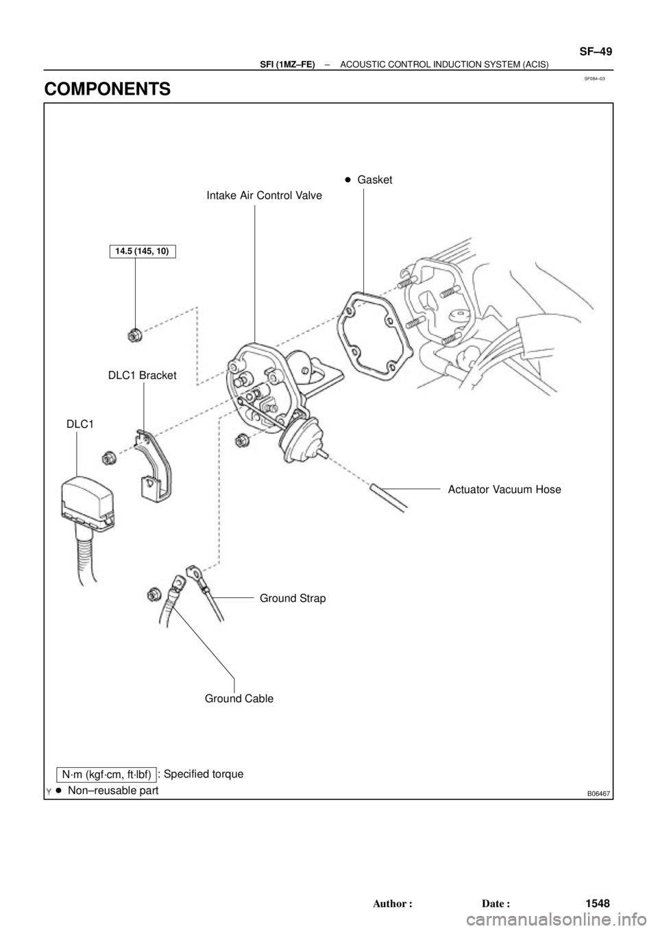
SF084±03
B06467
Intake Air Control Valve� Gasket
Actuator Vacuum Hose
Ground Strap
Ground Cable
: Specified torque
� Non±reusable part
14.5 (145, 10)
N´m (kgf´cm, ft´lbf)
DLC1 Bracket
DLC1
± SFI (1MZ±FE)ACOUSTIC CONTROL INDUCTION SYSTEM (ACIS)
SF±49
1548 Author�: Date�:
COMPONENTS
Page 3440 of 4592
SF087±03
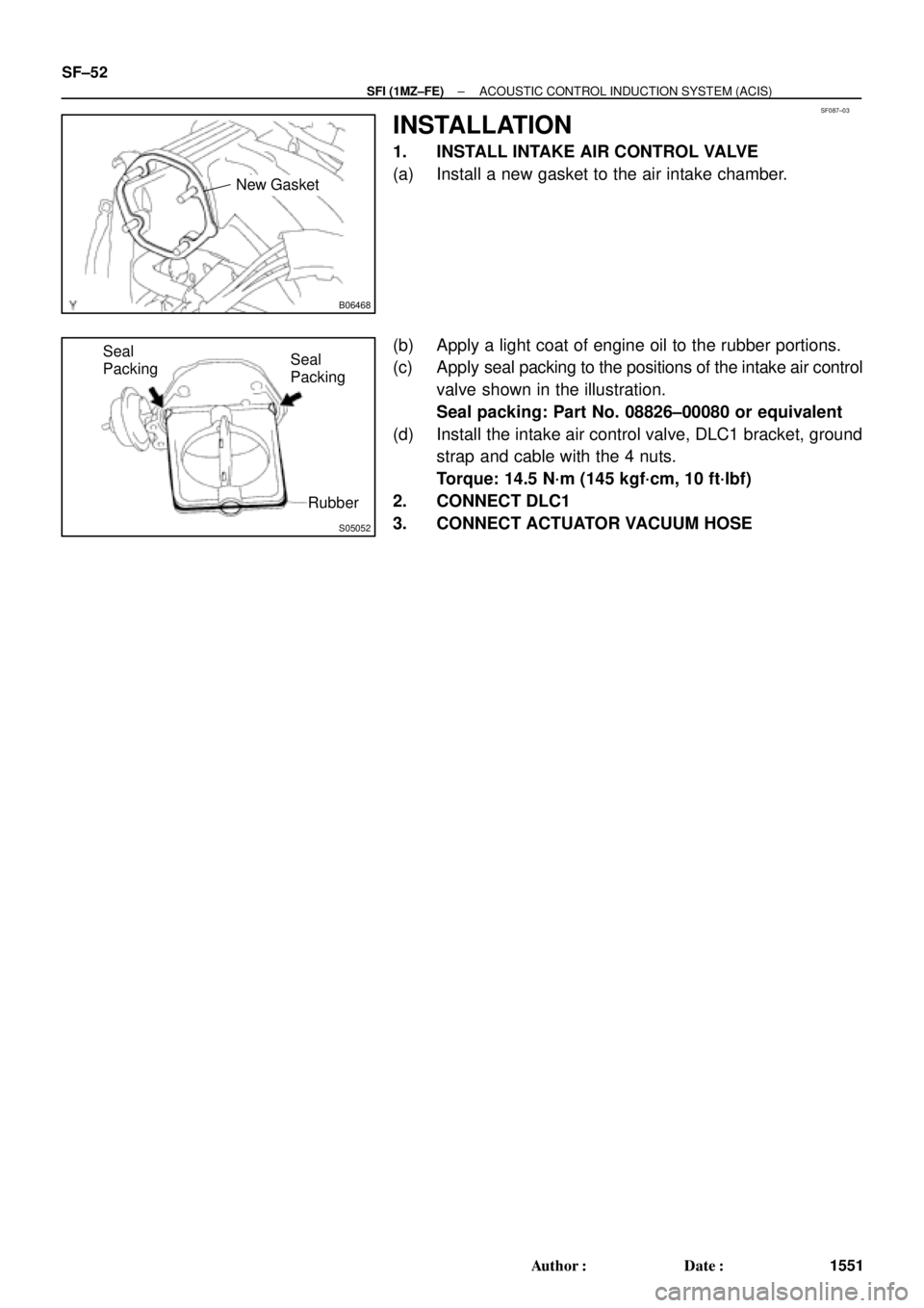
B06468
New Gasket
S05052
Seal
Packing
Rubber Seal
Packing SF±52
± SFI (1MZ±FE)ACOUSTIC CONTROL INDUCTION SYSTEM (ACIS)
1551 Author�: Date�:
INSTALLATION
1. INSTALL INTAKE AIR CONTROL VALVE
(a) Install a new gasket to the air intake chamber.
(b) Apply a light coat of engine oil to the rubber portions.
(c) Apply seal packing to the positions of the intake air control
valve shown in the illustration.
Seal packing: Part No. 08826±00080 or equivalent
(d) Install the intake air control valve, DLC1 bracket, ground
strap and cable with the 4 nuts.
Torque: 14.5 N´m (145 kgf´cm, 10 ft´lbf)
2. CONNECT DLC1
3. CONNECT ACTUATOR VACUUM HOSE
Page 3451 of 4592
SF08I±03
S04759
ECT Switch19 mm
Deep Socket
Wrench
Gasket
S01196S01699Z17274
Ohmmeter
Resistance kW
Temperature °C (°F) Acceptable 30
20
10
5
3
2
1
0.5
0.3
0.2
0.1
40 ±20 0 20 60 80 100
(212) (176) (140) (104) (68) (32) (±4)
± SFI (1MZ±FE)ENGINE COOLANT TEMPERATURE (ECT) SENSOR
SF±63
1562 Author�: Date�:
ENGINE COOLANT
TEMPERATURE (ECT) SENSOR
INSPECTION
1. DRAIN ENGINE COOLANT
2. REMOVE ECT SENSOR
(a) Disconnect the ECT sensor connector.
(b) Using a 19 mm deep socket wrench, remove the ECT
sensor and gasket.
3. INSPECT ECT SENSOR
Using an ohmmeter, measure the resistance between the ter-
minals.
Resistance: Refer to the graph
If the resistance is not as specified, replace the ECT sensor.
4. REINSTALL ECT SENSOR
(a) Install a new gasket to the ECT sensor.
(b) Using a 19 mm deep socket, install the ECT sensor.
Torque: 20 N´m (200 kgf´cm, 14 ft´lbf)
(c) Connect the ECT sensor connector.
5. REFILL WITH ENGINE COOLANT
 Acceptable 30
20
10
5
3
2
1
0.5
0.3
0.2
0.1
40 ±20 0 20 60 80 100
(212) (176")