Page 3471 of 4592
ST03J±01
± STARTING (5S±FE)STARTER
ST±5
1712 Author�: Date�:
REMOVAL
1. REMOVE BATTERY AND TRAY
2. w/ CRUISE CONTROL SYSTEM:
REMOVE CRUISE CONTROL ACTUATOR
(a) Disconnect the actuator connector and clamp.
(b) Remove the 3 bolts, and disconnect the actuator with the bracket.
3. REMOVE STARTER
(a) Disconnect the starter connector.
(b) Remove the 2 bolts, throttle cable clamp (A/T) and starter.
(c) Remove the nut, and disconnect the starter cable.
Torque: 37 N´m (380 kgf´cm, 27 ft´lbf)
Page 3472 of 4592

(4)
(3)
(2)
B01159
ST±6
± STARTING (5S±FE)STARTER
1713 Author�: Date�:
DISASSEMBLY
1. REMOVE DUST PROTECTOR
2. REMOVE FIELD FRAME AND")
ST03K±01
B01156
B01157
Protrusion
Identation
B01158
B01160
(1)
(4)
(3)
(2)
B01159
ST±6
± STARTING (5S±FE)STARTER
1713 Author�: Date�:
DISASSEMBLY
1. REMOVE DUST PROTECTOR
2. REMOVE FIELD FRAME AND ARMATURE
(a) Remove the nut, and disconnect the lead wire from the
magnetic switch terminal.
Torque: 5.9 N´m (60 kgf´cm, 52 in.´lbf)
(b) Remove the 2 through bolts.
Torque: 5.9 N´m (60 kgf´cm, 52 in.´lbf)
(c) Pull out the field frame together with the armature.
HINT:
Align the protrusion of the field frame with the identation of the
magnetic switch.
(d) Remove the O±ring from the field frame.
HINT:
At the time of installation, please refer to following items. Use
a new O±ring.
3. REMOVE STARTER HOUSING, CLUTCH
ASSEMBLY AND GEAR
(a) Remove the 2 screws.
Torque: 5.9 N´m (60 kgf´cm, 52 in.´lbf)
(b) Remove these parts from the magnetic switch:
(1) Starter housing and clutch assembly
(2) Return spring
(3) Idler gear
(4) Bearing
4. REMOVE STEEL BALL
Using a magnetic finger, remove the steel ball from the clutch
shaft hole.
Page 3473 of 4592
B01161
P13528
± STARTING (5S±FE)STARTER
ST±7
1714 Author�: Date�:
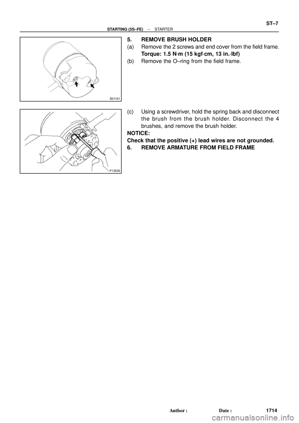
5. REMOVE BRUSH HOLDER
(a) Remove the 2 screws and end cover from the field frame.
Torque: 1.5 N´m (15 kgf´cm, 13 in.´lbf)
(b) Remove the O±ring from the field frame.
(c) Using a screwdriver, hold the spring back and disconnect
the brush from the brush holder. Disconnect the 4
brushes, and remove the brush holder.
NOTICE:
Check that the positive (+) lead wires are not grounded.
6. REMOVE ARMATURE FROM FIELD FRAME
Page 3482 of 4592
B01240
SST
B01241
ST±16
± STARTING (5S±FE)STARTER
1723 Author�: Date�: �
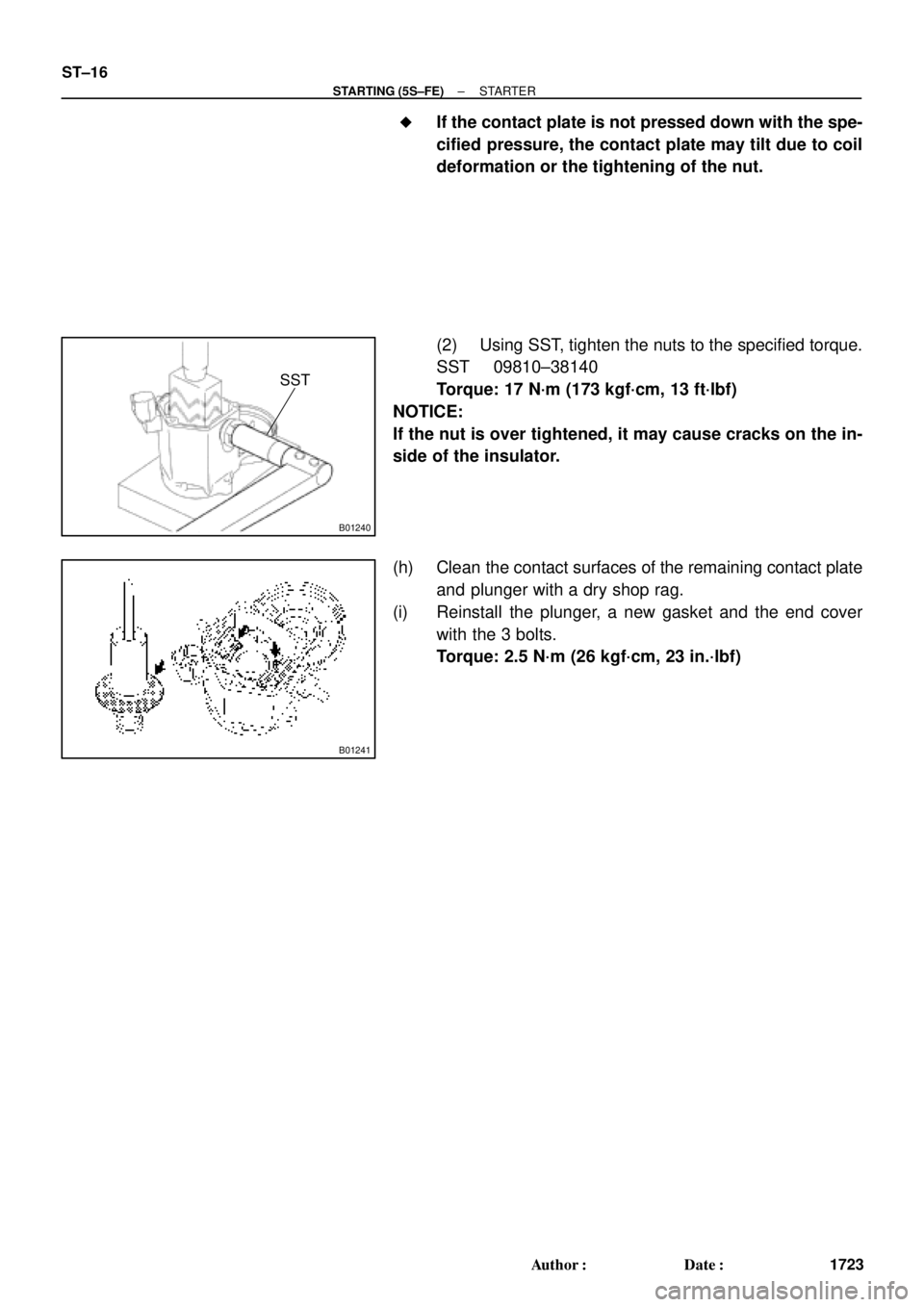
If the contact plate is not pressed down with the spe-
cified pressure, the contact plate may tilt due to coil
deformation or the tightening of the nut.
(2) Using SST, tighten the nuts to the specified torque.
SST 09810±38140
Torque: 17 N´m (173 kgf´cm, 13 ft´lbf)
NOTICE:
If the nut is over tightened, it may cause cracks on the in-
side of the insulator.
(h) Clean the contact surfaces of the remaining contact plate
and plunger with a dry shop rag.
(i) Reinstall the plunger, a new gasket and the end cover
with the 3 bolts.
Torque: 2.5 N´m (26 kgf´cm, 23 in.´lbf)
Page 3490 of 4592
B06418
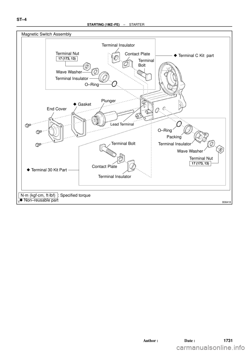
Magnetic Switch Assembly
Terminal Nut
Wave Washer
Terminal Insulator
O±RingContact Plate
Terminal
Bolt
Terminal Insulator� Terminal C Kit part
Plunger
� Gasket
End Cover
Lead Terminal
O±Ring
Packing
Terminal Insulator
Wave Washer
Terminal Nut Terminal Bolt
� Terminal 30 Kit PartContact PlateTerminal Insulator
N´m (kgf´cm, ft´lbf)
� Non±reusable part: Specified torque
17 (173, 13)
17 (173, 13)
ST±4
± STARTING (1MZ±FE)STARTER
1731 Author�: Date�:
Page 3491 of 4592
ST01V±03
± STARTING (1MZ±FE)STARTER
ST±5
1732 Author�: Date�:
REMOVAL
1. REMOVE BATTERY AND TRAY
2. w/ CRUISE CONTROL SYSTEM:
REMOVE CRUISE CONTROL ACTUATOR
(a) Disconnect the actuator connector and clamp.
(b) Remove the 3 bolts, and disconnect the actuator with the bracket.
3. REMOVE STARTER
(a) Disconnect the starter connector.
(b) Remove the 2 bolts, throttle cable clamp (A/T) and starter.
(c) Remove the nut, and disconnect the starter wire.
Torque: 37 N´m (380 kgf´cm, 27 ft´lbf)
Page 3492 of 4592

(4)
(3)
(2)
B01159
ST±6
± STARTING (1MZ±FE)STARTER
1733 Author�: Date�:
DISASSEMBLY
1. REMOVE DUST PROTECTOR
2. REMOVE FIELD FRAME AND")
ST01W±01
B01156
B01157
ProtrusionIdentation
B01158
B01160
(1)
(4)
(3)
(2)
B01159
ST±6
± STARTING (1MZ±FE)STARTER
1733 Author�: Date�:
DISASSEMBLY
1. REMOVE DUST PROTECTOR
2. REMOVE FIELD FRAME AND ARMATURE
(a) Remove the nut, and disconnect the lead wire from the
magnetic switch terminal.
Torque: 5.9 N´m (60 kgf´cm, 52 in.´lbf)
(b) Remove the 2 through bolts.
Torque: 5.9 N´m (60 kgf´cm, 52 in.´lbf)
(c) Pull out the field frame together with the armature.
HINT:
Align the protrusion of the field frame with the groove of the
magnetic switch.
(d) Remove the O±ring from the field frame.
HINT:
At the time of installation, please refer to the following items.
Use a new O±ring.
3. REMOVE STARTER HOUSING, CLUTCH
ASSEMBLY AND GEAR
(a) Remove the 2 screws.
Torque: 5.9 N´m (60 kgf´cm, 52 in.´lbf)
(b) Remove these parts from the magnetic switch:
(1) Starter housing and clutch assembly
(2) Return spring
(3) Idler gear
(4) Bearing
4. REMOVE STEEL BALL
Using a magnetic finger, remove the steel ball from the clutch
shaft hole.
Page 3493 of 4592
B01161
P13528
± STARTING (1MZ±FE)STARTER
ST±7
1734 Author�: Date�:
5. REMOVE BRUSH HOLDER
(a) Remove the 2 screws and end cover from the field frame.
Torque: 1.5 N´m (15 kgf´cm, 13 in.´lbf)
(b) Remove the O±ring from the field frame.
(c) Using a screwdriver, hold the spring back and disconnect
the brush from the brush holder. Disconnect the 4
brushes, and remove the brush holder.
NOTICE:
Check that the positive (+) lead wires are not grounded.
6. REMOVE ARMATURE FROM FIELD FRAME