Page 3539 of 4592
Z18921
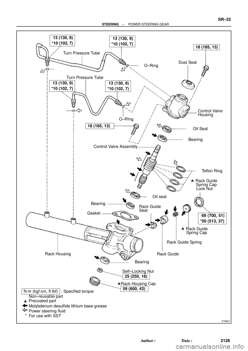
Turn Pressure Tube
� O±RingDust Seal
Turn Pressure Tube
� O±RIngControl Valve
Housing
� Oil Seal
� Bearing
� Teflon Ring
� Rack Guide
Spring Cap
Lock Nut
� Rack Guide
Spring Cap
Rack Guide Spring
Rack Guide
� Self±Locking Nut� Bearing
�Rack Housing Cap
N´m (kgf´cm, ft´lbf) : Specified torque
Non±reusable part
Precoated part
Molybdenum desulfide lithium base grease
Power steering fluid
For use with SSTRack Housing� Bearing
� GasketControl Valve Assembly � �
13 (130, 9)
*10 (102, 7) 13 (130, 9)
*10 (102, 7)
18 (185, 13)
69 (700, 51)
*50 (513, 37)
25 (250, 18)
59 (600, 43)
18 (185, 13)
13 (130, 9)
*10 (102, 7) 13 (130, 9)
*10 (102, 7)
�
�
*Rack Guide
Seat� Oil seal
± STEERINGPOWER STEERING GEAR
SR±33
2128 Author�: Date�:
Page 3551 of 4592
 Coat a new oil seal lip with power steering fluid.
(b) Using SST, pr")
W03562Oil Seal SST Press
R11648
SST
R11659
Punch
± STEERINGPOWER STEERING GEAR
SR±45
2140 Author�: Date�:
9. INSTALL OIL SEAL
(a) Coat a new oil seal lip with power steering fluid.
(b) Using SST, press in the oil seal.
SST 09612±22011
NOTICE:
Make sure to install the oil seal facing the correct direction.
10. INSTALL CONTROL VALVE HOUSING WITH CON-
TROL VALVE ASSEMBLY
(a) Place a new gasket on the rack housing.
(b) Align the matchmarks on the valve housing and rack
housing.
(c) Torque the 2 bolts.
Torque: 18 N´m (185 kgf´cm, 13 ft´lbf)
11. INSTALL SELF±LOCKING NUT
Using SST to stop the control valve shaft rotating, torque a new
nut.
SST 09616±00010
Torque: 25 N´m (250 kgf´cm, 18 ft´lbf)
12. INSTALL DUST COVER
13. INSTALL RACK HOUSING CAP
(a) Apply sealant to 2 or 3 threads of the cap.
Sealant:
Part No.08833±00080, THREE BOND 1344,
LOCTITE 242 or equivalent
(b) Torque the cap.
Torque: 59 N´m (600 kgf´cm, 43 ft´lbf)
(c) Using a punch and hammer, stake the 2 parts of the cap.
14. INSTALL RACK GUIDE SEAT, RACK GUIDE, RACK
GUIDE SPRING AND RACK GUIDE SPRING CAP
(a) Install the seat to the guide.
(b) Apply sealant to 2 or 3 threads of the cap.
Sealant:
Part No.08833±00080, THREE BOND 1344,
LOCTITE 242 or equivalent
(c) Temporarily install the cap.
Page 3552 of 4592
W03098
Rack Guide
Spring Cap
SST
W03099
12°
W03100
SST
W03101
Rack GuideSST
SST
Spring Cap SR±46
± STEERINGPOWER STEERING GEAR
2141 Author�: Date�:
15. ADJUST TOTAL PRELOAD
(a) To prevent the steering rack teeth from damaging the oil
seal lip, temporarily install the RH and LH rack ends.
(b) Using SST, torque the rack guide spring cap.
SST 09631±10021
Torque: 25 N´m (250 kgf´cm, 18 ft´lbf)
(c) Using SST, return the cap 12°.
SST 09631±10021
(d) Using SST, turn the control valve shaft right and left 1 or
2 times.
SST 09616±00010
(e) Using SST, loosen the cap until the rack guide spring is
not functioning.
SST 09631±10021
(f) Using SST and a torque wrench, tighten the cap until the
preload is within specification.
SST 09616±00010, 09631±10021
Preload (turning):
0.8 ± 1.4 N´m (8 ± 14 kgf´cm, 6.9 ± 12.2 in.´lbf)
Page 3553 of 4592

W03102
SST SST Rack Guide
Spring Cap
Lock NutFulcrum
Length
R11667
Claw
R15545
Fulcrum Length
SST
R11668
Brass Bar
± STEERINGPOWER STEERING GEAR
SR±47
2142 Author�: Date�:
16. INSTALL RACK GUIDE SPRING CAP LOCK NUT
(a) Apply sealant to 2 or 3 threads of the nut.
Sealant:
Part No.08833±00080, THREE BOND 1344,
LOCTITE 242 or equivalent
(b) Using SST to hold the rack guide spring cap, and using
SST, torque the nut.
SST 09631±10021, 09922±10010
Torque: 50 N´m (513 kgf´cm, 37 ft´lbf)
NOTICE:
Use SST 09922±10010 in the direction shown in the illustra-
tion.
HINT:
Use a torque wrench with a fulcrum length of 345 mm (13.58
in.).
(c) Recheck the total preload.
Preload (turning):
0.8 ± 1.4 N´m (8 ± 14 kgf´cm, 6.9 ± 12.2 in.´lbf)
(d) Remove the RH and LH rack ends.
17. INSTALL RH AND LH CLAW WASHERS AND RACK
ENDS
(a) Install a new claw washer, and temporarily install the rack
end.
HINT:
Align the claws of the washer with the steering rack grooves.
(b) Using a spanner (24 mm) to hold the steering rack steady,
and using SST, torque the rack end.
SST 09922±10010
Torque: 60 N´m (615 kgf´cm, 45 ft´lbf)
NOTICE:
Use SST 09922±10010 in the direction shown in the illustra-
tion.
HINT:
Use a torque wrench with a fulcrum length of 345 mm (13.58
in.).
(c) Using a brass bar and hammer, stake the washer.
NOTICE:
Avoid any impact to the rack.
Page 3554 of 4592

or less
SST
W04231
Fulcrum
LengthSST SR±48
± STEERINGPOWER STEERING GEAR
2143 Author�: Date�:
18. INSTALL RH AND LH RACK BOOTS, CLAMPS AND
CLIPS
(a) Ensure that the ste")
R11669
W04223
2 mm
(0.79 in.)
or less
SST
W04231
Fulcrum
LengthSST SR±48
± STEERINGPOWER STEERING GEAR
2143 Author�: Date�:
18. INSTALL RH AND LH RACK BOOTS, CLAMPS AND
CLIPS
(a) Ensure that the steering rack hole is not clogged with
grease.
HINT:
If the hole is clogged, the pressure inside the boot will change
after it is assembled and the steering wheel is turned.
(b) Install the boot.
NOTICE:
Be careful not to damage or twist the boot.
(c) Using SST, tighten the clamp as shown in the illustration.
SST 09521±24010
19. INSTALL RH AND LH TIE ROD ENDS AND LOCK NUTS
(a) Screw the lock nut and tie rod end onto the rack end until
the matchmarks are aligned.
(b) After adjusting toe±in, torque the nut.
(See page SA±4)
Torque: 74 N´m (750 kgf´cm, 54 ft´lbf)
20. INSTALL 2 TURN PRESSURE TUBES
(a) Coat 2 new O±rings with power steering fluid and install
them to the tube.
(b) Using SST, install the tube.
SST 09633±00020
Torque: 10 N´m (102 kgf´cm, 7 ft´lbf)
HINT:
�Use a torque wrench with a fulcrum length of 250 mm
(9.84 in.).
�This torque value is effective in case that SST is parallel
to a torque wrench.
Page 3555 of 4592
 Install the gear assembly from the LH of the vehicle.
NOTICE")
SR06Y±01
W04224
SST
Fulcrum
Length
± STEERINGPOWER STEERING GEAR
SR±49
2144 Author�: Date�:
INSTALLATION
1. INSTALL PS GEAR ASSEMBLY
(a) Install the gear assembly from the LH of the vehicle.
NOTICE:
Do not damage the turn pressure tubes.
(b) Torque the 2 gear assembly set bolts and nuts.
Torque: 181 N´m (1,850 kgf´cm, 134 ft´lbf)
HINT:
Lift up the stabilizer bar and install the bolts.
2. INSTALL NO.1 FUEL TUBE PROTECTOR
Install the 2 bolts and nut.
3. CONNECT STABILIZER BAR
Torque the 4 bolts.
Torque: 19 N´m (195 kgf´cm, 14 ft´lbf)
4. CONNECT PRESSURE FEED AND RETURN TUBES
Using SST, connect the tube.
SST 09631±22020
Torque: 32 N´m (326 kgf´cm, 24 ft´lbf)
HINT:
�Use a torque wrench with a fulcrum length of 300 mm
(11.81 in.).
�This torque value is effective in case that SST is parallel
to a torque wrench.
5. CONNECT CLAMP PLATE
Torque the nut.
Torque: 10 N´m (100 kgf´cm, 7 ft´lbf)
6. CONNECT INTERMEDIATE SHAFT ASSEMBLY
(See page SR±16)
7. CONNECT RH AND LH TIE ROD ENDS
(See page SA±10)
8. POSITION FRONT WHEELS FACING STRAIGHT
AHEAD
HINT:
Do it with the front of the vehicle jacked up.
9. CENTER SPIRAL CABLE
(See page SR±16)
10. INSTALL STEERING WHEEL
(a) Install the wheel at straight±ahead position.
(b) Temporarily tighten the wheel set nut.
(c) Connect the connector.
11. BLEED POWER STEERING SYSTEM
(See page SR±4)
12. CHECK STEERING WHEEL CENTER POINT
Page 3556 of 4592
SR±50
± STEERINGPOWER STEERING GEAR
2145 Author�: Date�:
13. TORQUE STEERING WHEEL SET NUT
Torque: 35 N´m (360 kgf´cm, 26 ft´lbf)
14. INSTALL STEERING WHEEL PAD
(See page SR±16)
15. CHECK FRONT WHEEL ALIGNMENT
(See page SA±4)
Page 3561 of 4592

W03086
F02267
1
2
F01195
Bolt
Adjusting
ValueSet Bolt
15'
30'Adjusting Bolt90105±15001 90105±15004 90105±15005 90105±15006
45'
1°00'
1°15'
1°30'121212121 Dot 2 Dots 3 Dots
± SUSPENSION AND AXLEFRONT WHEEL ALIGNMENT
SA±5
1956 Author�: Date�:
5. ADJUST CAMBER
NOTICE:
After the camber has been adjusted, inspect the toe±in.
(a) Remove the front wheels and speed sensor clamp.
(b) Remove the 2 nuts on the lower side of the shock absorb-
er.
(c) Coat the threads of the nuts with engine oil.
(d) Temporarily install the 2 nuts.
(e) Adjust the camber by pushing or pulling the lower side of
the shock absorber in the direction in which the camber
adjustment is required.
(f) Tighten the nuts.
Torque: 211 N´m (2,150 kgf´cm, 156 ft´lbf)
(g) Install the front wheels.
Torque: 103 N´m (1,050 kgf´cm, 76 ft´lbf)
(h) Check the camber.
HINT:
�Try to adjust the camber to the center value.
�Adjusting value for the set bolts is 6' ± 30' (0.1° ± 0.5°).
If the camber is not within the specification, using the table be-
low, estimate for how much additional camber adjustment will
be required, and select the camber adjusting bolt.
(i) Follow the above mentioned steps again. Between step
(b) and (c), exchange 1 or 2 selected bolts.
HINT:
When exchanging the 2 bolts, exchange 1 bolt for each time.