Page 1093 of 4592
CH02X±01
Z18635
Z18636
B02378
P13597SST (B)
SST (A) Turn
P10834
SST (B)
SST (C)
Insert
± CHARGING (5S±FE)GENERATOR
CH±7
1754 Author�: Date�:
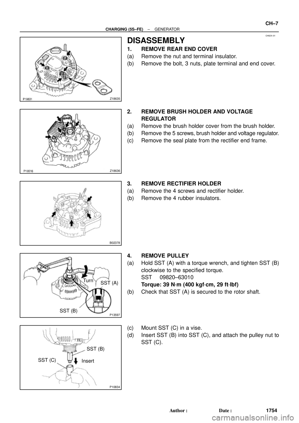
DISASSEMBLY
1. REMOVE REAR END COVER
(a) Remove the nut and terminal insulator.
(b) Remove the bolt, 3 nuts, plate terminal and end cover.
2. REMOVE BRUSH HOLDER AND VOLTAGE
REGULATOR
(a) Remove the brush holder cover from the brush holder.
(b) Remove the 5 screws, brush holder and voltage regulator.
(c) Remove the seal plate from the rectifier end frame.
3. REMOVE RECTIFIER HOLDER
(a) Remove the 4 screws and rectifier holder.
(b) Remove the 4 rubber insulators.
4. REMOVE PULLEY
(a) Hold SST (A) with a torque wrench, and tighten SST (B)
clockwise to the specified torque.
SST 09820±63010
Torque: 39 N´m (400 kgf´cm, 29 ft´lbf)
(b) Check that SST (A) is secured to the rotor shaft.
(c) Mount SST (C) in a vise.
(d) Insert SST (B) into SST (C), and attach the pulley nut to
SST (C).
Page 1097 of 4592
CH02Z±01
CH0827
P00100
Socket Wrench
P13479
Downward SST
N00581
SST
P13567
± CHARGING (5S±FE)GENERATOR
CH±11
1758 Author�: Date�:
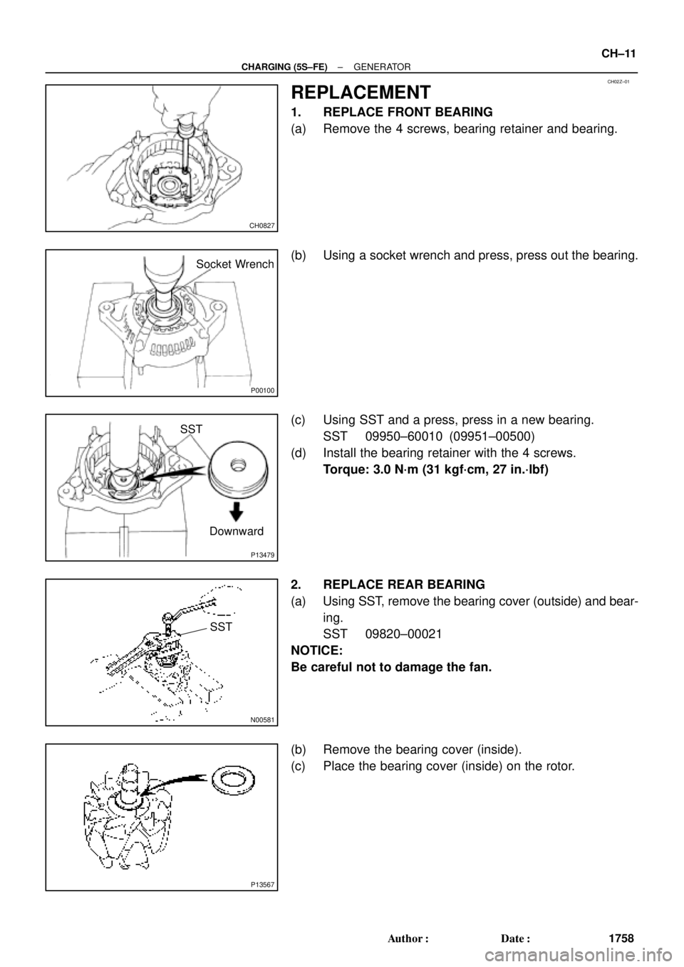
REPLACEMENT
1. REPLACE FRONT BEARING
(a) Remove the 4 screws, bearing retainer and bearing.
(b) Using a socket wrench and press, press out the bearing.
(c) Using SST and a press, press in a new bearing.
SST 09950±60010 (09951±00500)
(d) Install the bearing retainer with the 4 screws.
Torque: 3.0 N´m (31 kgf´cm, 27 in.´lbf)
2. REPLACE REAR BEARING
(a) Using SST, remove the bearing cover (outside) and bear-
ing.
SST 09820±00021
NOTICE:
Be careful not to damage the fan.
(b) Remove the bearing cover (inside).
(c) Place the bearing cover (inside) on the rotor.
Page 1099 of 4592
CH030±01
P01364
Pulley
Z18637
P13487
29 mm
Socket
Wrench
Z19213
A B
AA
P13597
SST (A) Turn
SST (B)
± CHARGING (5S±FE)GENERATOR
CH±13
1760 Author�: Date�:
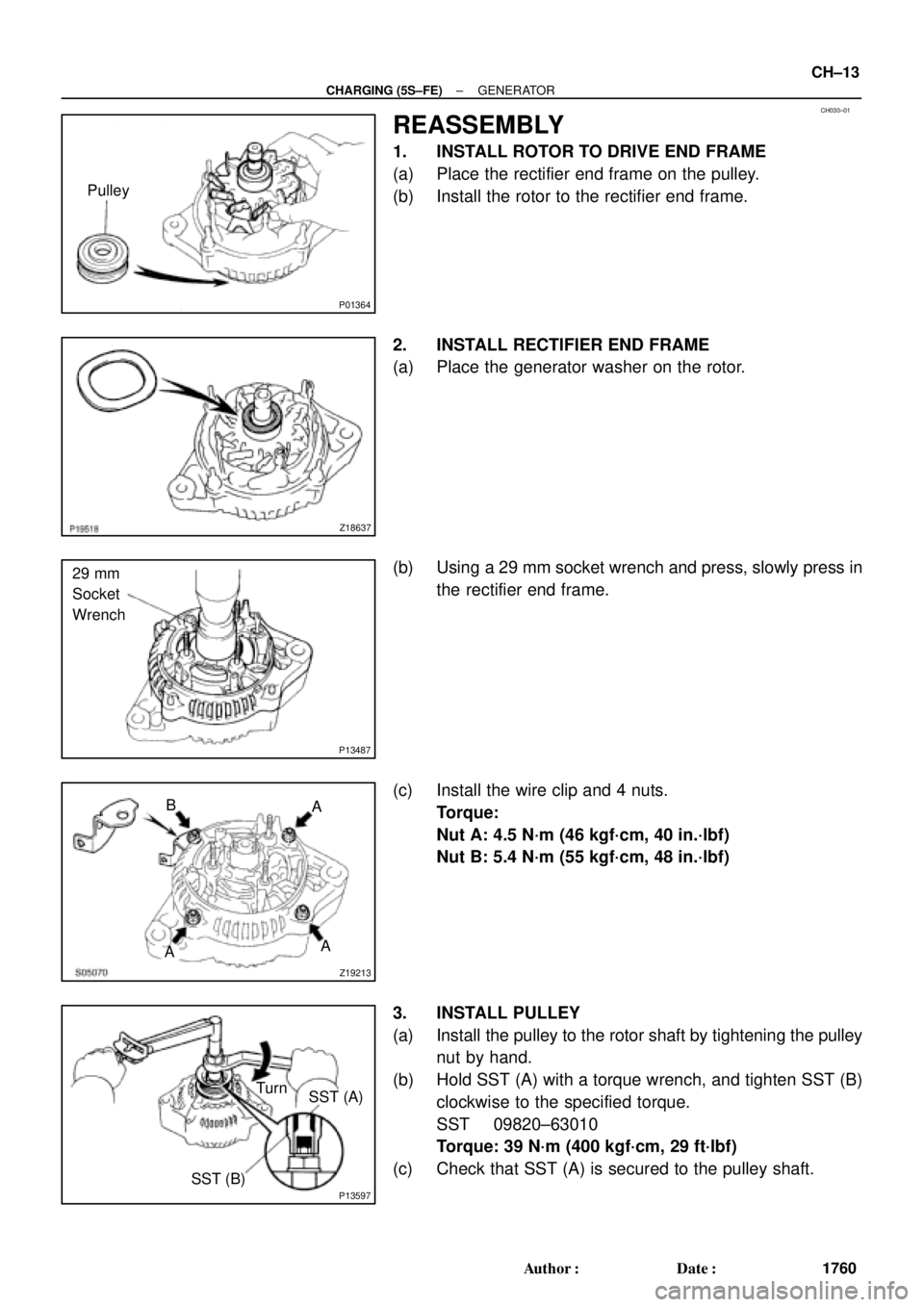
REASSEMBLY
1. INSTALL ROTOR TO DRIVE END FRAME
(a) Place the rectifier end frame on the pulley.
(b) Install the rotor to the rectifier end frame.
2. INSTALL RECTIFIER END FRAME
(a) Place the generator washer on the rotor.
(b) Using a 29 mm socket wrench and press, slowly press in
the rectifier end frame.
(c) Install the wire clip and 4 nuts.
Torque:
Nut A: 4.5 N´m (46 kgf´cm, 40 in.´lbf)
Nut B: 5.4 N´m (55 kgf´cm, 48 in.´lbf)
3. INSTALL PULLEY
(a) Install the pulley to the rotor shaft by tightening the pulley
nut by hand.
(b) Hold SST (A) with a torque wrench, and tighten SST (B)
clockwise to the specified torque.
SST 09820±63010
Torque: 39 N´m (400 kgf´cm, 29 ft´lbf)
(c) Check that SST (A) is secured to the pulley shaft.
Page 1100 of 4592
P04210
SST (C)
P04395
SST (C)
SST (A) Turn
P13598SST (B)SST (A) Turn
S05075
Inside
S05074
Push CH±14
± CHARGING (5S±FE)GENERATOR
1761 Author�: Date�:
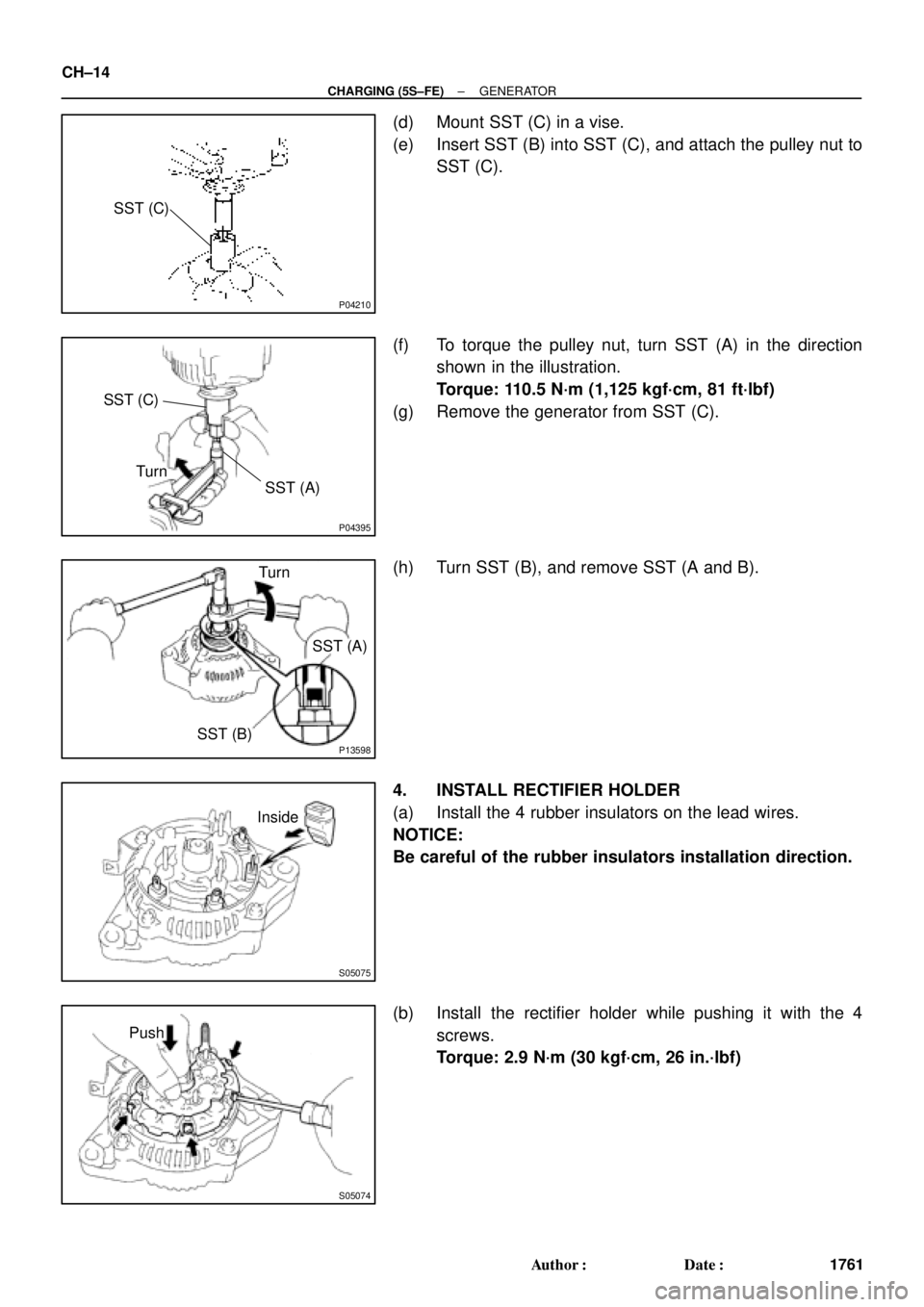
(d) Mount SST (C) in a vise.
(e) Insert SST (B) into SST (C), and attach the pulley nut to
SST (C).
(f) To torque the pulley nut, turn SST (A) in the direction
shown in the illustration.
Torque: 110.5 N´m (1,125 kgf´cm, 81 ft´lbf)
(g) Remove the generator from SST (C).
(h) Turn SST (B), and remove SST (A and B).
4. INSTALL RECTIFIER HOLDER
(a) Install the 4 rubber insulators on the lead wires.
NOTICE:
Be careful of the rubber insulators installation direction.
(b) Install the rectifier holder while pushing it with the 4
screws.
Torque: 2.9 N´m (30 kgf´cm, 26 in.´lbf)
Page 1101 of 4592
Z18638
S05461
Upward
Z18640
Z18635
S05069
± CHARGING (5S±FE)GENERATOR
CH±15
1762 Author�: Date�:
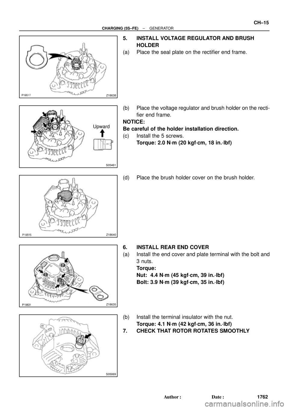
5. INSTALL VOLTAGE REGULATOR AND BRUSH
HOLDER
(a) Place the seal plate on the rectifier end frame.
(b) Place the voltage regulator and brush holder on the recti-
fier end frame.
NOTICE:
Be careful of the holder installation direction.
(c) Install the 5 screws.
Torque: 2.0 N´m (20 kgf´cm, 18 in.´lbf)
(d) Place the brush holder cover on the brush holder.
6. INSTALL REAR END COVER
(a) Install the end cover and plate terminal with the bolt and
3 nuts.
Torque:
Nut: 4.4 N´m (45 kgf´cm, 39 in.´lbf)
Bolt: 3.9 N´m (39 kgf´cm, 35 in.´lbf)
(b) Install the terminal insulator with the nut.
Torque: 4.1 N´m (42 kgf´cm, 36 in.´lbf)
7. CHECK THAT ROTOR ROTATES SMOOTHLY
Page 1108 of 4592
CH01F±01
P14226
Pivot Bolt
Adjusting
Lock BoltAdjusting Bolt
P14227
CH±6
± CHARGING (1MZ±FE)GENERATOR
1769 Author�: Date�:
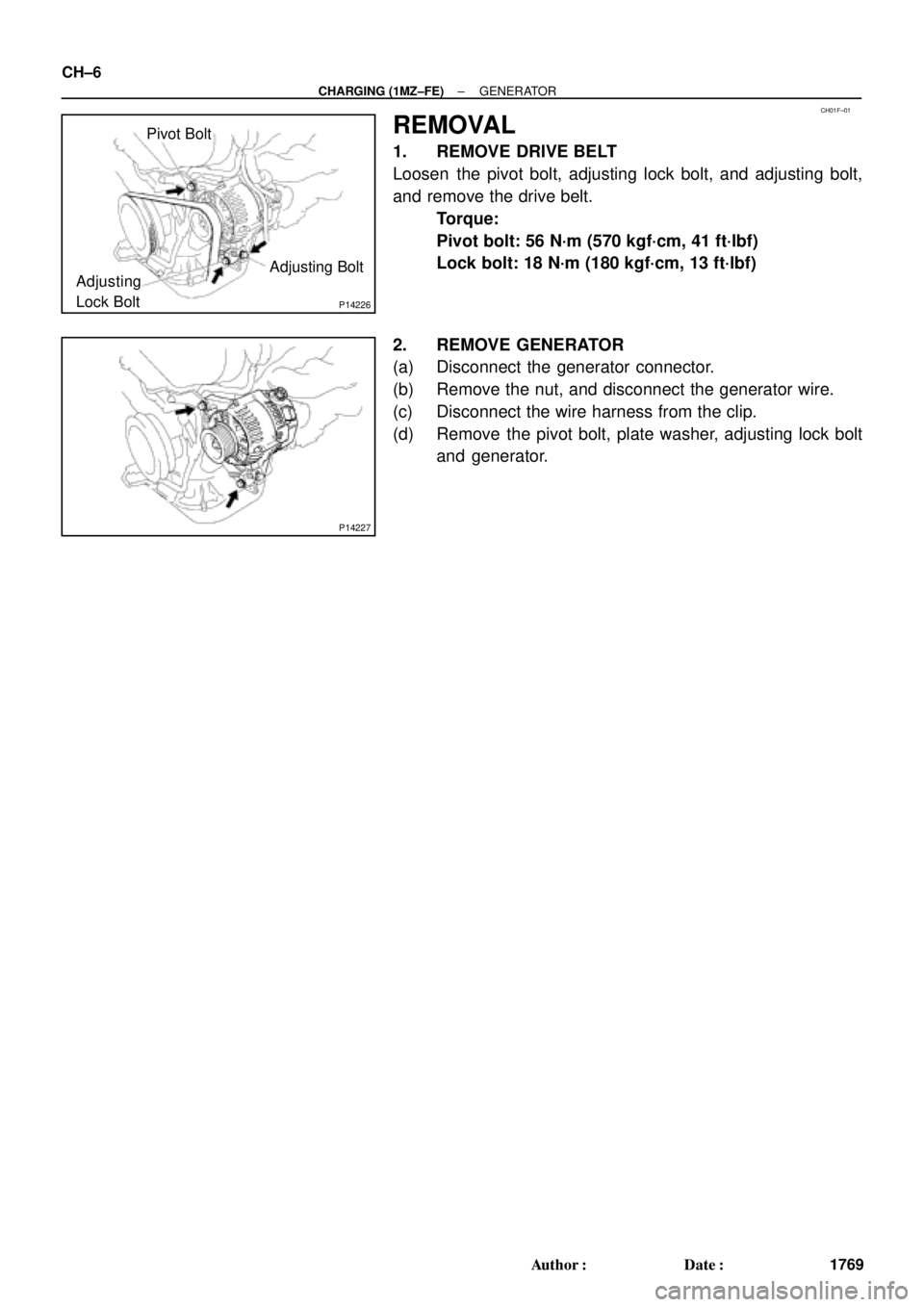
REMOVAL
1. REMOVE DRIVE BELT
Loosen the pivot bolt, adjusting lock bolt, and adjusting bolt,
and remove the drive belt.
Torque:
Pivot bolt: 56 N´m (570 kgf´cm, 41 ft´lbf)
Lock bolt: 18 N´m (180 kgf´cm, 13 ft´lbf)
2. REMOVE GENERATOR
(a) Disconnect the generator connector.
(b) Remove the nut, and disconnect the generator wire.
(c) Disconnect the wire harness from the clip.
(d) Remove the pivot bolt, plate washer, adjusting lock bolt
and generator.
Page 1109 of 4592
CH01G±01
P14233
Plate Terminal
P14234
S05072
P10835
SST (B)SST (A) Turn
P10834
SST (C)SST (B)
Insert
± CHARGING (1MZ±FE)GENERATOR
CH±7
1770 Author�: Date�:
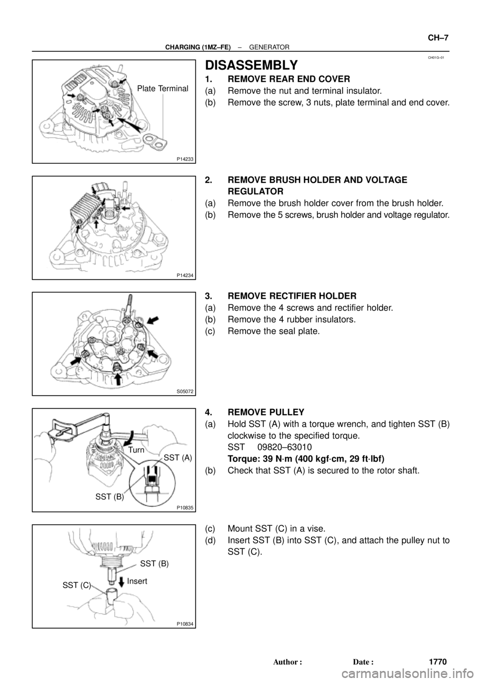
DISASSEMBLY
1. REMOVE REAR END COVER
(a) Remove the nut and terminal insulator.
(b) Remove the screw, 3 nuts, plate terminal and end cover.
2. REMOVE BRUSH HOLDER AND VOLTAGE
REGULATOR
(a) Remove the brush holder cover from the brush holder.
(b) Remove the 5 screws, brush holder and voltage regulator.
3. REMOVE RECTIFIER HOLDER
(a) Remove the 4 screws and rectifier holder.
(b) Remove the 4 rubber insulators.
(c) Remove the seal plate.
4. REMOVE PULLEY
(a) Hold SST (A) with a torque wrench, and tighten SST (B)
clockwise to the specified torque.
SST 09820±63010
Torque: 39 N´m (400 kgf´cm, 29 ft´lbf)
(b) Check that SST (A) is secured to the rotor shaft.
(c) Mount SST (C) in a vise.
(d) Insert SST (B) into SST (C), and attach the pulley nut to
SST (C).
Page 1113 of 4592
CH01I±01
P14225
P00628
Socket Wrench
P00479
SST
N00581
SST
P13567
± CHARGING (1MZ±FE)GENERATOR
CH±11
1774 Author�: Date�:
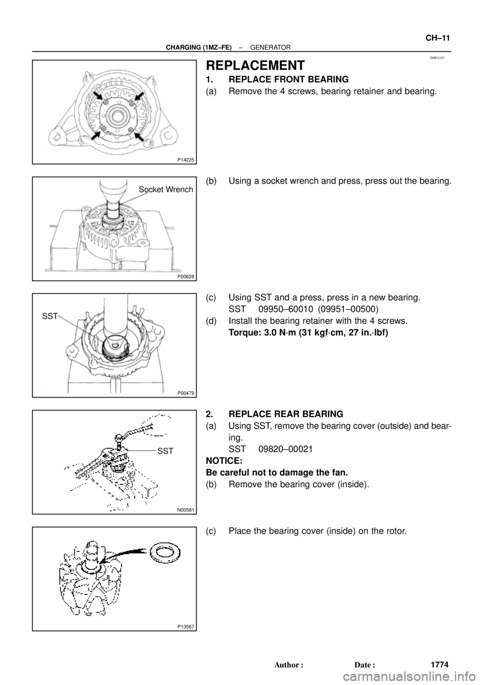
REPLACEMENT
1. REPLACE FRONT BEARING
(a) Remove the 4 screws, bearing retainer and bearing.
(b) Using a socket wrench and press, press out the bearing.
(c) Using SST and a press, press in a new bearing.
SST 09950±60010 (09951±00500)
(d) Install the bearing retainer with the 4 screws.
Torque: 3.0 N´m (31 kgf´cm, 27 in.´lbf)
2. REPLACE REAR BEARING
(a) Using SST, remove the bearing cover (outside) and bear-
ing.
SST 09820±00021
NOTICE:
Be careful not to damage the fan.
(b) Remove the bearing cover (inside).
(c) Place the bearing cover (inside) on the rotor.