Page 1182 of 4592
CO0SO±01
P12942
CO±8
± COOLING (1MZ±FE)WATER PUMP
1616 Author�: Date�:
INSTALLATION
1. INSTALL WATER PUMP
Install a new gasket and the water pump with the 4 bolts and 2
nuts.
Torque: 8 N´m (80 kgf´cm, 69 in.´lbf)
NOTICE:
Do not get oil on the gasket.
2. INSTALL NO.3 TIMING BELT COVER
(See page EM±57)
3. INSTALL NO.2 IDLER PULLEY
(See page EM±21)
4. INSTALL CAMSHAFT TIMING PULLEYS
(See page EM±21)
5. INSTALL TIMING BELT
(See page EM±21)
6. FILL WITH ENGINE COOLANT
7. START ENGINE AND CHECK FOR LEAKS
8. RECHECK ENGINE COOLANT LEVEL
Page 1183 of 4592
CO03H±03
B06397
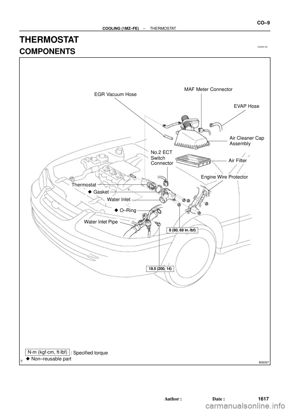
MAF Meter Connector
EVAP Hose
Air Cleaner Cap
Assembly
Engine Wire Protector
Thermostat
� Gasket
Water Inlet
Water Inlet Pipe
� O±Ring
No.2 ECT
Switch
Connector
8 (80, 69 in.´lbf)
19.5 (200, 14)
Air Filter EGR Vacuum Hose
N´m (kgf´cm, ft´lbf)
: Specified torque
� Non±reusable part
± COOLING (1MZ±FE)THERMOSTAT
CO±9
1617 Author�: Date�:
THERMOSTAT
COMPONENTS
Page 1186 of 4592
THERMOSTAT
1620 Author�: Date�:
INSTALLATION
1. PLACE THERMOSTAT IN WATER PUMP
(a) Install a new gasket on to the thermostat.")
CO03K±03
S04532
Jiggle Valve
Stud Bolt15°15° CO±12
± COOLING (1MZ±FE)THERMOSTAT
1620 Author�: Date�:
INSTALLATION
1. PLACE THERMOSTAT IN WATER PUMP
(a) Install a new gasket on to the thermostat.
(b) Align the thermostat jiggle valve with the upper stud bolt,
and insert the thermostat in the water inlet housing.
HINT:
The jiggle valve may be set within 15° of either side of the pre-
scribed position.
2. INSTALL WATER INLET
Install the water inlet with the 3 nuts.
Torque: 8 N´m (80 kgf´cm, 69 in.´lbf)
3. INSTALL WATER INLET PIPE
(a) Install a new O±ring to the water inlet pipe.
(b) Apply soapy water to the O±ring.
(c) Connect the water inlet pipe to the water inlet.
(d) Install the bolt holding the water inlet pipe to the cylinder
head.
Torque: 19.5 N´m (200 kgf´cm, 14 ft´lbf)
4. INSTALL ENGINE WIRE PROTECTOR
5. CONNECT NO.2 ECT SWITCH CONNECTOR
6. REINSTALL AIR FILTER AND AIR CLEANER CAP
ASSEMBLY
7. FILL WITH ENGINE COOLANT
8. START ENGINE AND CHECK FOR LEAKS
9. RECHECK ENGINE COOLANT LEVEL
Page 1192 of 4592
RADIATOR
1626 Author�: Date�:
REMOVAL
HINT:
�At the time of installation, please refer to the following
items.
�Start the")
CO03O±03
S04725
B05937
Lower
Hose
Oil
Cooler
Hose
CO±18
± COOLING (1MZ±FE)RADIATOR
1626 Author�: Date�:
REMOVAL
HINT:
�At the time of installation, please refer to the following
items.
�Start the engine, and check for coolant and A/T fluid
leaks.
�Check the A/T fluid level. (See page DI±438)
1. DRAIN ENGINE COOLANT
2. CANADA:
DISCONNECT RELAY BLOCK (FOR DAYTIME
RUNNING LIGHT SYSTEM) FROM BATTERY
HOLD±DOWN CLAMP
3. DISCONNECT UPPER RADIATOR HOSE FROM
RADIATOR
4. DISCONNECT LOWER RADIATOR HOSE FROM
WATER INLET PIPE
5. DISCONNECT A/T OIL COOLER HOSES FROM OIL
COOLER PIPES
6. DISCONNECT NO.1 AND NO.2 COOLING FAN
CONNECTORS
7. DISCONNECT NO.1 ECT SWITCH WIRE CONNECTOR
8. REMOVE RADIATOR AND COOLING FANS
ASSEMBLY
(a) Remove the 2 bolts and 2 upper supports.
Torque: 12.8 N´m (130 kgf´cm, 9 ft´lbf)
(b) Lift out the radiator, and remove the radiator and cooling
fans assembly.
(c) Remove the 2 lower supports.
9. REMOVE A/T OIL COOLER HOSES FROM
RADIATOR
10. REMOVE LOWER RADIATOR HOSE FROM
RADIATOR
Page 1193 of 4592
S04588
B05938
No.1No.2
± COOLING (1MZ±FE)RADIATOR
CO±19
1627 Author�: Date�:
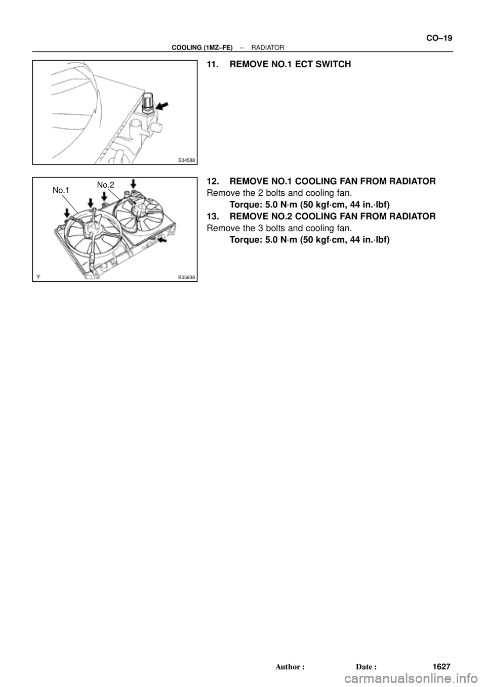
11. REMOVE NO.1 ECT SWITCH
12. REMOVE NO.1 COOLING FAN FROM RADIATOR
Remove the 2 bolts and cooling fan.
Torque: 5.0 N´m (50 kgf´cm, 44 in.´lbf)
13. REMOVE NO.2 COOLING FAN FROM RADIATOR
Remove the 3 bolts and cooling fan.
Torque: 5.0 N´m (50 kgf´cm, 44 in.´lbf)
Page 1195 of 4592

(2)
(3)(4)(5) (6)
CO1267
Lock Plate
Lock Plate
Core
CO0317
O±Ring� Normal
X Twisted
X Twisted
± COOLING (1MZ±FE)RADIATOR
CO±21
1629 Author�: Date�:
REASSEMBLY
1. A/T:
INST")
CO03Q±03
Z18506
A/T
(1)
(2)
(3)(4)(5) (6)
CO1267
Lock Plate
Lock Plate
Core
CO0317
O±Ring� Normal
X Twisted
X Twisted
± COOLING (1MZ±FE)RADIATOR
CO±21
1629 Author�: Date�:
REASSEMBLY
1. A/T:
INSTALL OIL COOLER TO LOWER TANK
(a) Clean the O±ring contact surface of the lower tank and oil
cooler.
(b) Install a new O±rings (1) to the oil cooler (2).
(c) Install the oil cooler with the O±rings to the lower tank (3).
(d) Install the plate washers (4), and nuts (5). Torque the
nuts.
Torque: 8.3 N´m (85 kgf´cm, 74 in.´lbf)
(e) Install the pipe (6).
Torque: 14.7 N´m (150 kgf´cm, 11 ft´lbf)
2. INSPECT LOCK PLATE
Inspect the lock plate for damage.
HINT:
�If the sides of the lock plate groove are deformed, reas-
sembly of the tank will be impossible.
�Therefore, first correct any deformation with pliers or simi-
lar object. Water leakage will result if the bottom of the
lock plate groove is damaged or dented, Therefore, repair
or replace if necessary.
NOTICE:
The radiator can only be recaulked 2 times. After the 2nd
time, the radiator core must be replaced.
3. INSTALL NEW O±RINGS AND TANKS
(a) After checking that there are no foreign objects in the lock
plate groove, install the new O±ring without twisting it.
HINT:
When cleaning the lock plate groove, lightly rub it with sand pa-
per without scratching it.
Page 1203 of 4592
CO03U±03
B05943
B05944
± COOLING (1MZ±FE)ELECTRIC COOLING FAN
CO±29
1637 Author�: Date�:
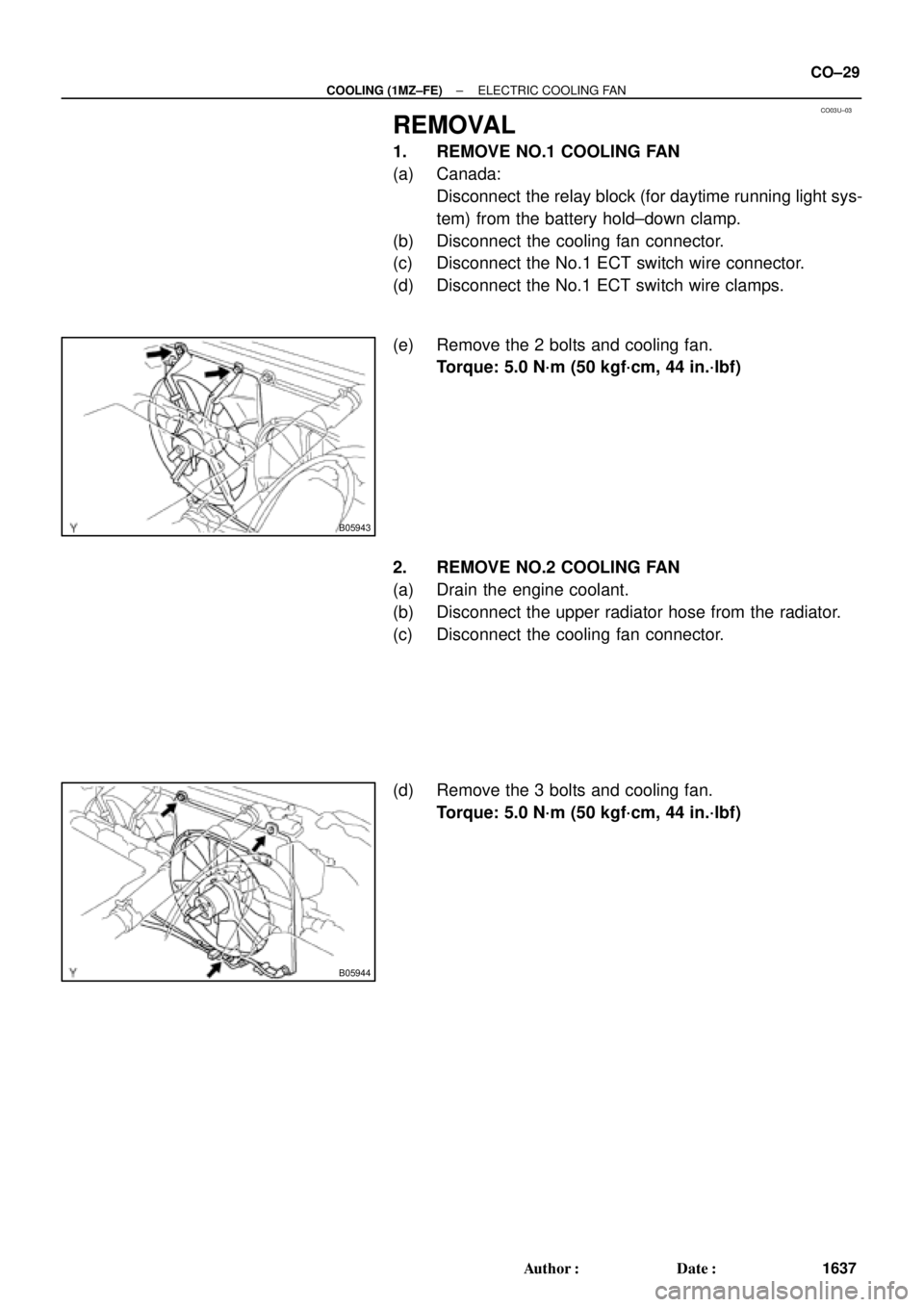
REMOVAL
1. REMOVE NO.1 COOLING FAN
(a) Canada:
Disconnect the relay block (for daytime running light sys-
tem) from the battery hold±down clamp.
(b) Disconnect the cooling fan connector.
(c) Disconnect the No.1 ECT switch wire connector.
(d) Disconnect the No.1 ECT switch wire clamps.
(e) Remove the 2 bolts and cooling fan.
Torque: 5.0 N´m (50 kgf´cm, 44 in.´lbf)
2. REMOVE NO.2 COOLING FAN
(a) Drain the engine coolant.
(b) Disconnect the upper radiator hose from the radiator.
(c) Disconnect the cooling fan connector.
(d) Remove the 3 bolts and cooling fan.
Torque: 5.0 N´m (50 kgf´cm, 44 in.´lbf)
Page 1605 of 4592

DI±393
628 Author�: Date�:
(b) Clearance the DTC.
The following actions will erase the DTC and freeze frame
data. Operating an OBD II scan tool (complying w")
± DIAGNOSTICSAUTOMATIC TRANSAXLE (A140E)
DI±393
628 Author�: Date�:
(b) Clearance the DTC.
The following actions will erase the DTC and freeze frame
data. Operating an OBD II scan tool (complying with SAE
J1978) or TOYOTA hand±held tester to erase the codes.
(See the OBD II scan tool's instruction book for operating
instructions.)
4. ROAD TEST
NOTICE:
Perform the test at normal operating ATF temperature 50 ± 80 °C (122 ± 176 °F).
(a) D position test
Shift into the D position and fully depress the accelerator pedal and and check the following points:
(1) Check up±shift operation.
1 " 2, 2 " 3 and 3 " O/D up±shifts take place, at the shift point shown in the automatic shift
schedule (See page SS±54).
HINT:
�O/D Gear Up±shift Prohibition Control (1. Coolant temp. is 50 °C (122 °C) or less. 2. If there is a 10
km/h (6 mph) difference between the set cruise control speed and vehicle speed.)
�O/D Gear Lock±up Prohibition Control (1. Brake pedal is depressed. 2. Coolant temp. is 50 °C
(122 °C) or less.)
(2) Check for shift shock and slip.
Check for shock and slip at the 1 " 2, 2 " 3 and 3 " O/D up±shifts.
(3) Check for abnormal noises and vibration.
Run at the D position lock±up or O/D gear and check for abnormal noises and vibration.
HINT:
The check for the cause of abnormal noises and vibration must be done very thoroughly as it could also be
due to loss of balance in the differential or torque converter clutch, etc.
(4) Check kick±down operation.
While running in the D position, 2nd, 3rd and O/D gears, check to see that the possible kick±down
vehicle speed limits for 2 " 1, 3 " 2 and O/D " 3 kick±downs conform to those indicated on
the automatic shift schedule (See page SS±54).
(5) Check abnormal shock and slip at kick±down.
(6) Check the lock±up mechanism.
�Drive in D position, O/D gear, at a steady speed (lock±up ON) of about 75 km/h (47 mph).
�Lightly depress the accelerator pedal and check that the engine speed does not change
abruptly.
If there is a big jump in engine speed, there is no lock±up.
(b) 2 position test
Shift into the 2 position and fully depress the accelerator pedal and check the following points:
(1) Check up±shift operation.
Check to see that the 1 " 2 up±shift takes place and that the shift point conforms to the automatic
shift schedule (See page SS±54).
HINT:
There is no O/D up±shift and lock±up in the 2 position.
(2) Check engine braking.
While running in the 2 position and 2nd gear, release the accelerator pedal and check the engine
braking effect.