Page 1115 of 4592
CH01J±01
P01364
Pulley
P00427
P01763
29 mm
Socket
Wrench
Z19214AA A
B
P10835
Turn
SST (A)
SST (B)
± CHARGING (1MZ±FE)GENERATOR
CH±13
1776 Author�: Date�:
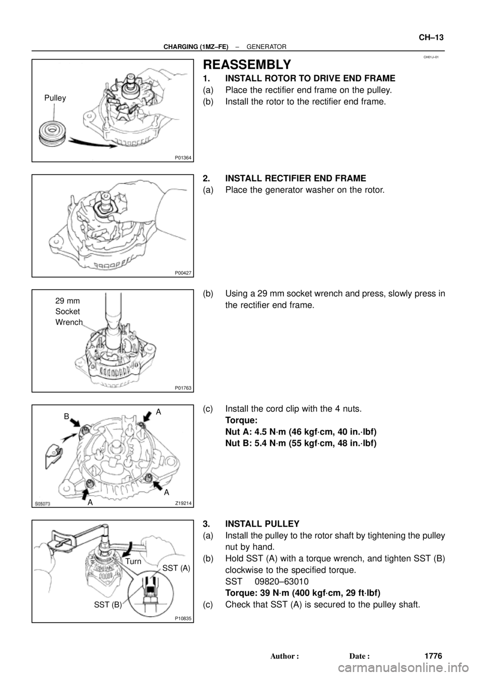
REASSEMBLY
1. INSTALL ROTOR TO DRIVE END FRAME
(a) Place the rectifier end frame on the pulley.
(b) Install the rotor to the rectifier end frame.
2. INSTALL RECTIFIER END FRAME
(a) Place the generator washer on the rotor.
(b) Using a 29 mm socket wrench and press, slowly press in
the rectifier end frame.
(c) Install the cord clip with the 4 nuts.
Torque:
Nut A: 4.5 N´m (46 kgf´cm, 40 in.´lbf)
Nut B: 5.4 N´m (55 kgf´cm, 48 in.´lbf)
3. INSTALL PULLEY
(a) Install the pulley to the rotor shaft by tightening the pulley
nut by hand.
(b) Hold SST (A) with a torque wrench, and tighten SST (B)
clockwise to the specified torque.
SST 09820±63010
Torque: 39 N´m (400 kgf´cm, 29 ft´lbf)
(c) Check that SST (A) is secured to the pulley shaft.
Page 1116 of 4592
P10834
SST (C)SST (A)
Insert
P10829
SST (C)
SST (A)
Turn
P10836
SST (B)SST (A) Turn
P00428
P00645
CH±14
± CHARGING (1MZ±FE)GENERATOR
1777 Author�: Date�:
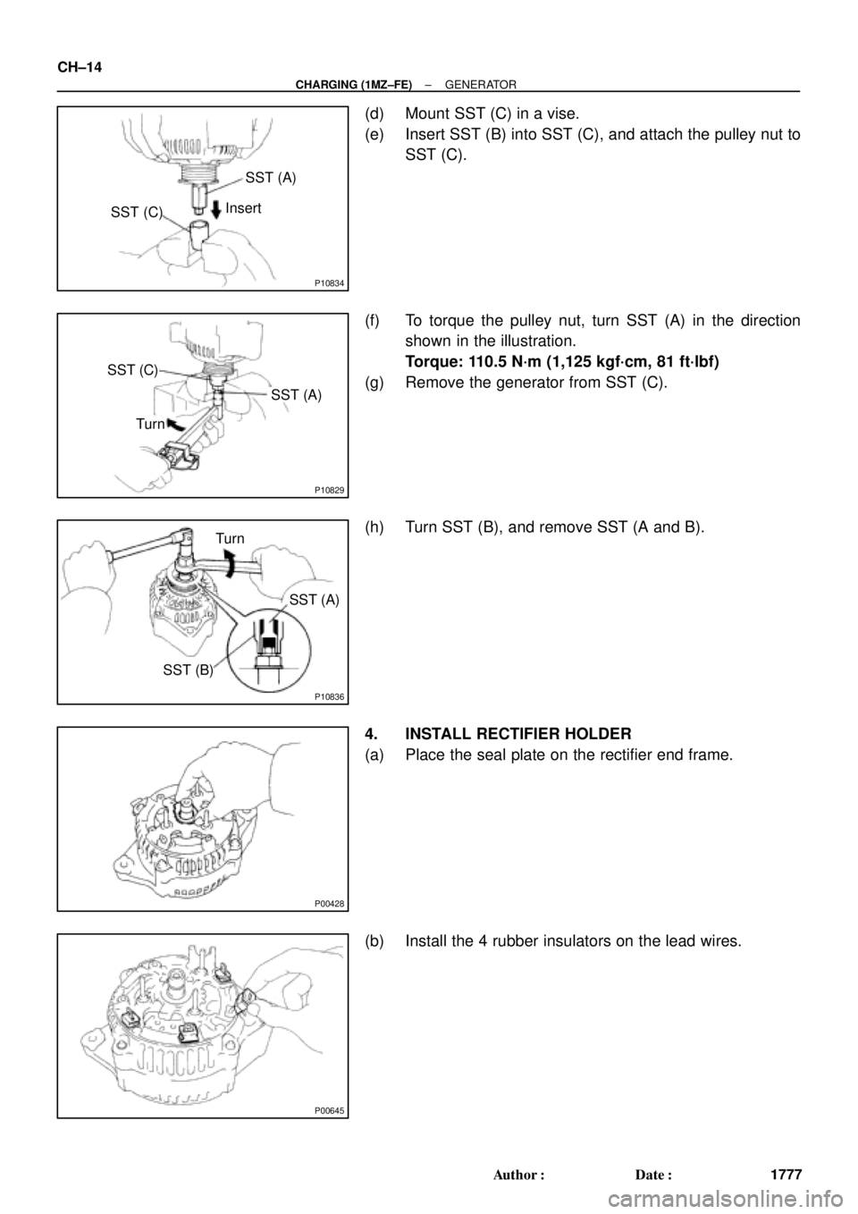
(d) Mount SST (C) in a vise.
(e) Insert SST (B) into SST (C), and attach the pulley nut to
SST (C).
(f) To torque the pulley nut, turn SST (A) in the direction
shown in the illustration.
Torque: 110.5 N´m (1,125 kgf´cm, 81 ft´lbf)
(g) Remove the generator from SST (C).
(h) Turn SST (B), and remove SST (A and B).
4. INSTALL RECTIFIER HOLDER
(a) Place the seal plate on the rectifier end frame.
(b) Install the 4 rubber insulators on the lead wires.
Page 1117 of 4592
S05072
S05460
Upward
P14235
P14233
Plate Terminal
S05071
± CHARGING (1MZ±FE)GENERATOR
CH±15
1778 Author�: Date�:
(c) Install the rectifier holder with the 4 screws.
Torque: 2.9 N´m (30 kgf´cm, 26 in.´lbf)
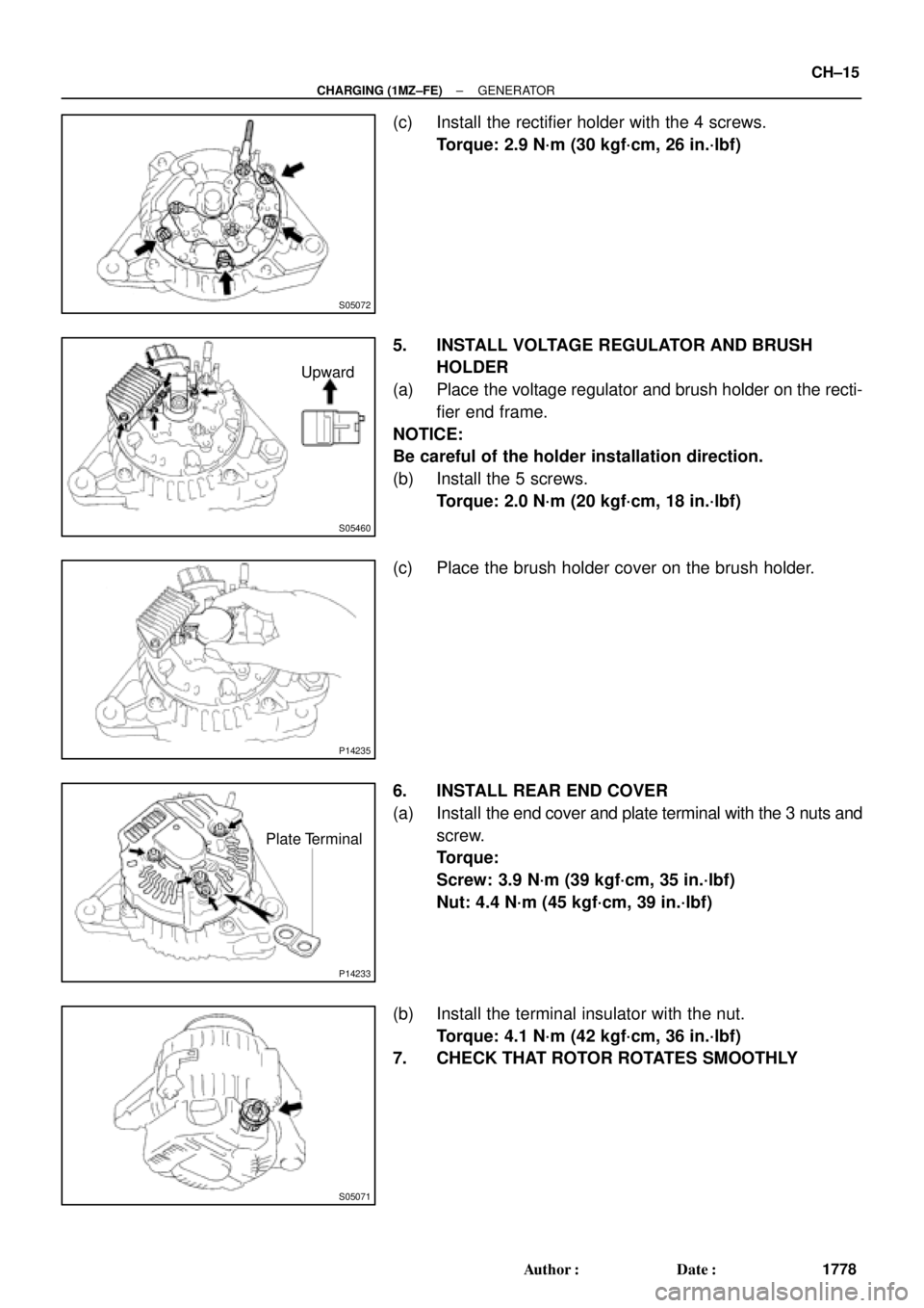
5. INSTALL VOLTAGE REGULATOR AND BRUSH
HOLDER
(a) Place the voltage regulator and brush holder on the recti-
fier end frame.
NOTICE:
Be careful of the holder installation direction.
(b) Install the 5 screws.
Torque: 2.0 N´m (20 kgf´cm, 18 in.´lbf)
(c) Place the brush holder cover on the brush holder.
6. INSTALL REAR END COVER
(a) Install the end cover and plate terminal with the 3 nuts and
screw.
Torque:
Screw: 3.9 N´m (39 kgf´cm, 35 in.´lbf)
Nut: 4.4 N´m (45 kgf´cm, 39 in.´lbf)
(b) Install the terminal insulator with the nut.
Torque: 4.1 N´m (42 kgf´cm, 36 in.´lbf)
7. CHECK THAT ROTOR ROTATES SMOOTHLY
Page 1122 of 4592
CL036±01
Q10085
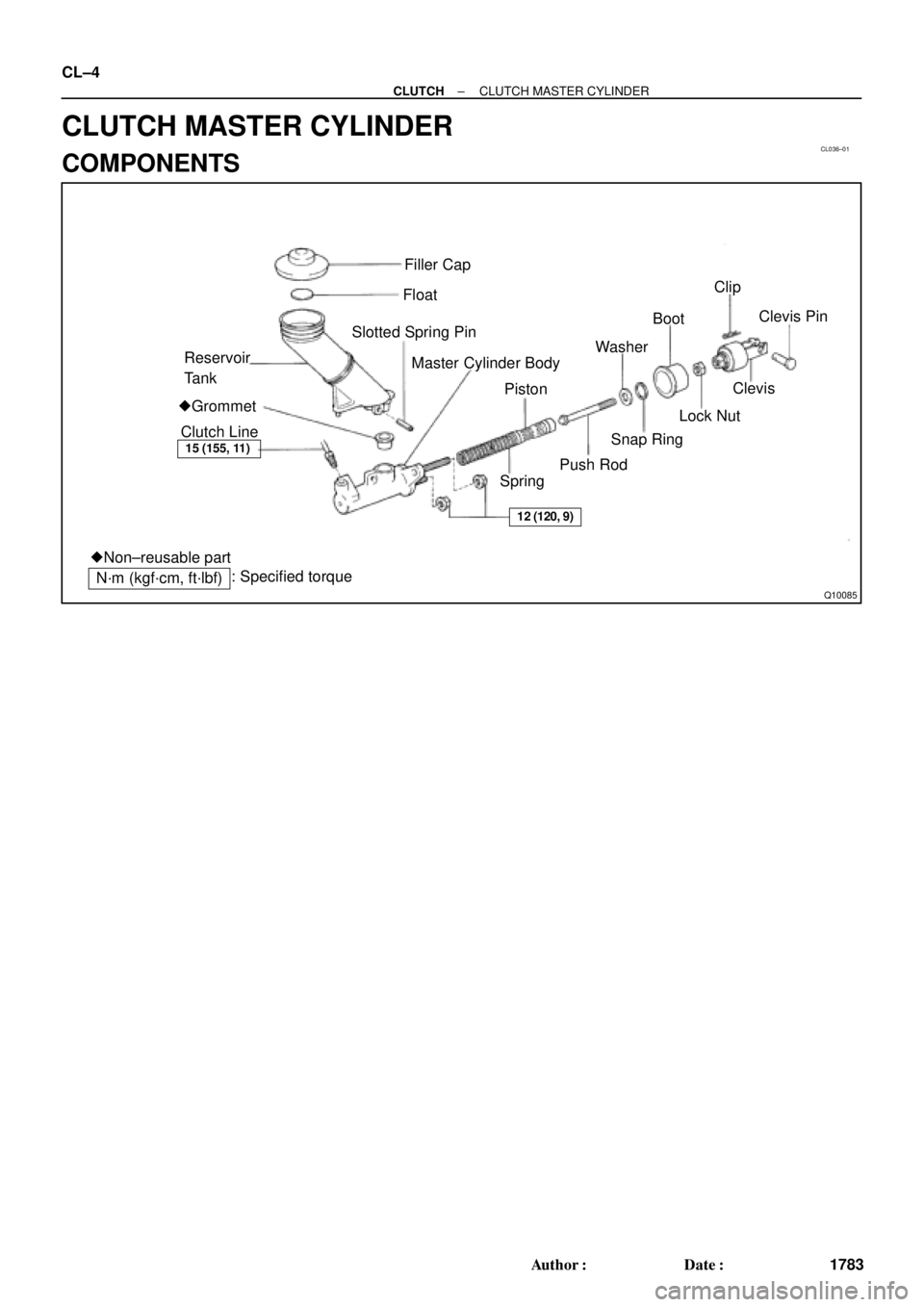
Filler Cap
Float
Reservoir
TankSlotted Spring Pin
�Grommet
Clutch Line
15 (155, 11)
Master Cylinder Body
�Non±reusable part
N´m (kgf´cm, ft´lbf): Specified torqueSpringPiston
Push RodSnap Ring WasherBootClip
12 (120, 9)
Lock NutClevisClevis Pin CL±4
± CLUTCHCLUTCH MASTER CYLINDER
1783 Author�: Date�:
CLUTCH MASTER CYLINDER
COMPONENTS
Page 1123 of 4592
CL037±01
Q10094
SST
± CLUTCHCLUTCH MASTER CYLINDER
CL±5
1784 Author�: Date�:
REMOVAL
1. DRAW OUT FLUID WITH SYRINGE
2. DISCONNECT CLUTCH LINE
Using SST, disconnect the clutch line. Use a container to catch
the fluid.
SST 09023±00100
Torque: 15 N´m (155 kgf´cm, 11 ft´lbf)
3. REMOVE CLIP AND CLEVIS PIN
4. REMOVE 2 MOUNTING NUTS AND PULL OUT MAS-
TER CYLINDER
Torque: 12 N´m (120 kgf´cm, 9 ft´lbf)
Page 1127 of 4592
CL03B±01
Q10016
Clutch Line
15 (155, 11)
12 (120, 9)
Bleeder Plug
8.4 (85, 74 in.´lbf)
Release Cylinder Body
Piston
Spring
Push RodBoot
N´m (kgf´cm, ft´lbf)
: Specified torque
± CLUTCHCLUTCH RELEASE CYLINDER
CL±9
1788 Author�: Date�:
CLUTCH RELEASE CYLINDER
COMPONENTS
Page 1128 of 4592
CL03C±01
Q10077
SST CL±10
± CLUTCHCLUTCH RELEASE CYLINDER
1789 Author�: Date�:
REMOVAL
1. DISCONNECT CLUTCH LINE
Using SST, disconnect the line. Use a container to catch the
fluid.
SST 09023±00100
Torque: 15 N´m (155 kgf´cm, 11 ft´lbf)
2. REMOVE 2 BOLTS AND PULL OUT RELEASE CYL-
INDER
Torque: 12 N´m (120 kgf´cm, 9 ft´lbf)
Page 1130 of 4592
CL03E±01
Q06048
CL±12
± CLUTCHCLUTCH RELEASE CYLINDER
1791 Author�: Date�:
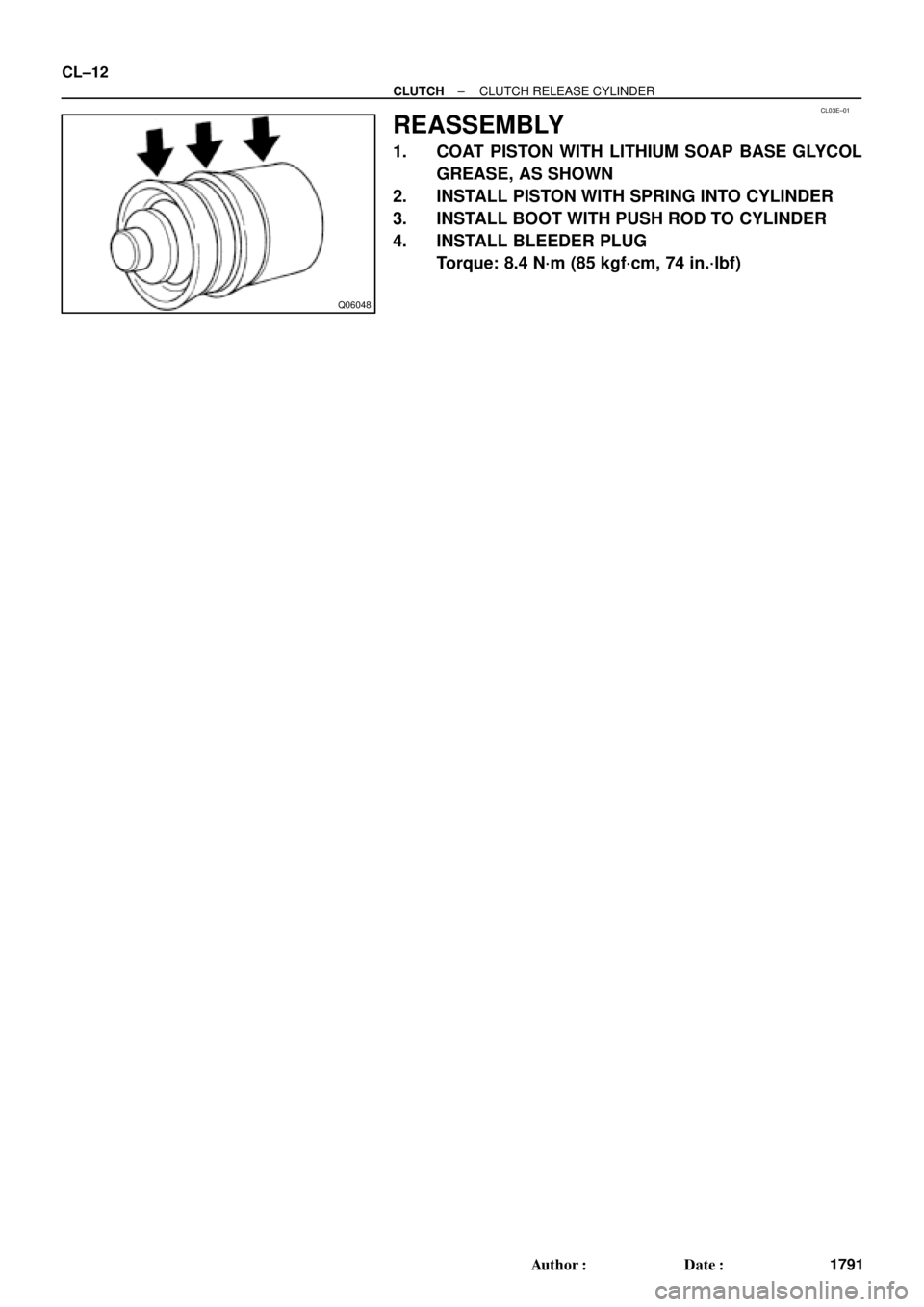
REASSEMBLY
1. COAT PISTON WITH LITHIUM SOAP BASE GLYCOL
GREASE, AS SHOWN
2. INSTALL PISTON WITH SPRING INTO CYLINDER
3. INSTALL BOOT WITH PUSH ROD TO CYLINDER
4. INSTALL BLEEDER PLUG
Torque: 8.4 N´m (85 kgf´cm, 74 in.´lbf)


12 (120, 9)
Bleeder Plug
8.4 (85, 74 in.´lbf)
Release Cylinder Body
Piston
Spring
Push RodBoot
N´m (kgf´cm, ft´lbf)
: Specified torque
± CLUTCHCLUTCH REL")