Page 1153 of 4592
CO0SN±01
P13611
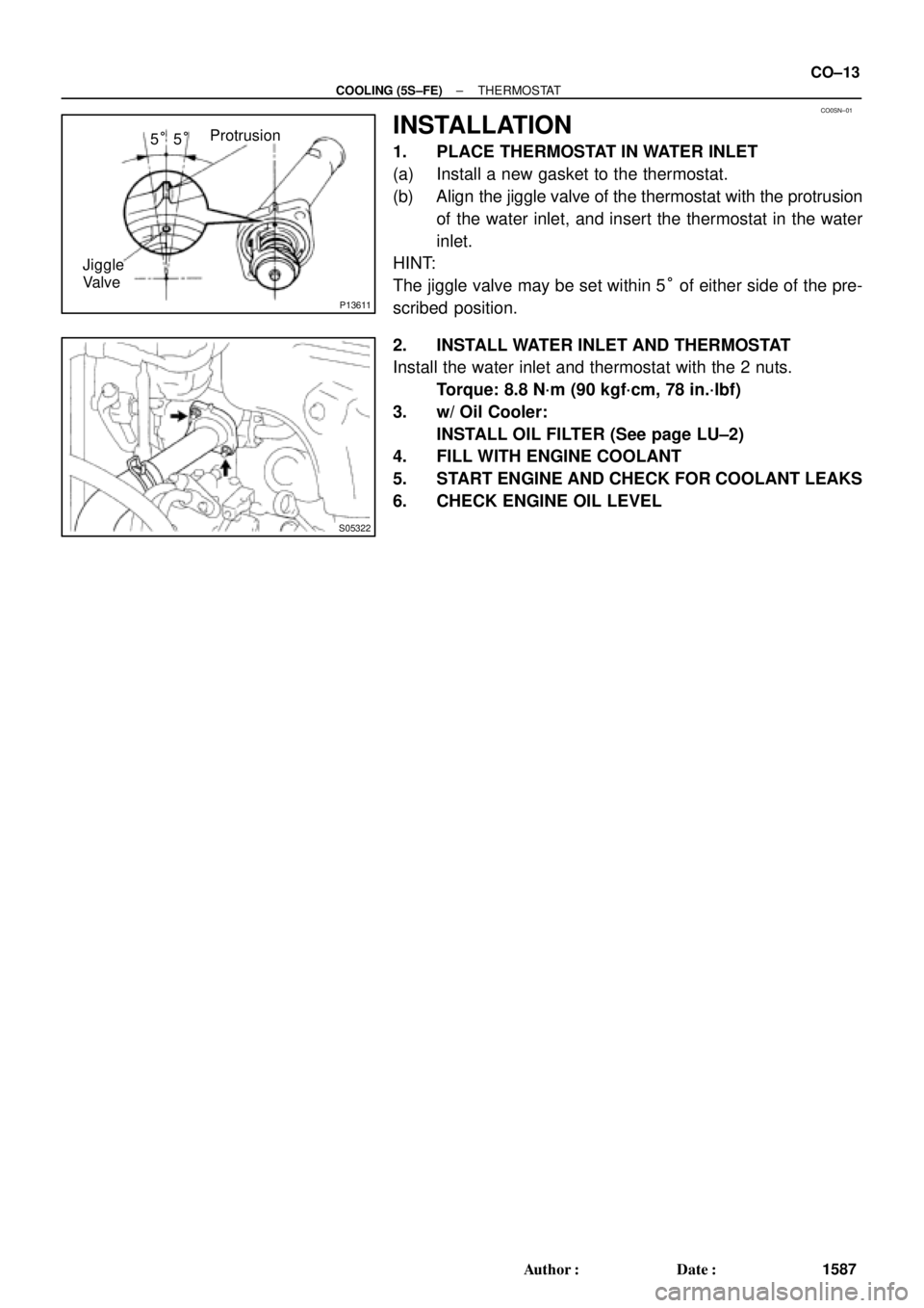
Protrusion
Jiggle
Valve5°5°
S05322
± COOLING (5S±FE)THERMOSTAT
CO±13
1587 Author�: Date�:
INSTALLATION
1. PLACE THERMOSTAT IN WATER INLET
(a) Install a new gasket to the thermostat.
(b) Align the jiggle valve of the thermostat with the protrusion
of the water inlet, and insert the thermostat in the water
inlet.
HINT:
The jiggle valve may be set within 5° of either side of the pre-
scribed position.
2. INSTALL WATER INLET AND THERMOSTAT
Install the water inlet and thermostat with the 2 nuts.
Torque: 8.8 N´m (90 kgf´cm, 78 in.´lbf)
3. w/ Oil Cooler:
INSTALL OIL FILTER (See page LU±2)
4. FILL WITH ENGINE COOLANT
5. START ENGINE AND CHECK FOR COOLANT LEAKS
6. CHECK ENGINE OIL LEVEL
Page 1160 of 4592
RADIATOR
1594 Author�:")
CO06L±04
S05307
DownwardPipe
18°
CO1267
Lock Plate
CoreLock Plate
CO0317
� Normal
O±RingX Twisted
X Twisted
S04698
Ta pWRONG
CORRECT
Tank
Lock
Plate CO±20
± COOLING (5S±FE)RADIATOR
1594 Author�: Date�:
REASSEMBLY
1. A/T:
INSTALL OIL COOLER TO LOWER TANK
(a) Install 2 new O±rings to the oil cooler.
(b) Install the oil cooler to the lower tank with the 2 plate
washers and nuts.
Torque: 8.3 N´m (85 kgf´cm, 74 in.´lbf)
(c) Install the cooler pipe in the direction indicated in the il-
lustration.
Torque: 14.7 N´m (150 kgf´cm, 11 ft´lbf)
2. INSPECT LOCK PLATE FOR DAMAGE
HINT:
�If the sides of the lock plate groove are deformed, reas-
sembly of the tank will be impossible.
�Therefore, first correct any deformation with pliers or simi-
lar object. Water leakage will result if the bottom of the
lock plate groove is damaged or dented.
NOTICE:
The radiator can only be recaulked 2 times. After the 2nd
time, the radiator core must be replaced.
3. INSTALL NEW O±RINGS AND TANKS
(a) After checking that there are no foreign objects in the lock
plate groove, install the new O±ring without twisting it.
HINT:
When cleaning the lock plate groove, lightly rub it with sand pa-
per without scratching it.
(b) Install the tank without damaging the O±ring.
(c) Tap the lock plate with a soft±faced hammer so that there
is no gap between it and the tank.
Page 1163 of 4592
RADIATOR
CO±23
1597 Author�: Date�:
INSTALLATION
1. INSTALL NO.1 ELECTRIC COOLING FAN TO RADIA-
TOR
(a) Attach the lower side of the cooling fan to the bracket of")
CO06M±03
S05955
± COOLING (5S±FE)RADIATOR
CO±23
1597 Author�: Date�:
INSTALLATION
1. INSTALL NO.1 ELECTRIC COOLING FAN TO RADIA-
TOR
(a) Attach the lower side of the cooling fan to the bracket of
the radiator.
(b) Install the cooling fan with the 2 bolts.
(c) Connect the ECT switch connector for the cooling fan.
(d) Install the ECT switch wire clamp for the cooling fan to the
bracket of the radiator.
Torque: 5.0 N´m (50 kgf´cm, 44 in.´lbf)
2. INSTALL NO.2 ELECTRIC COOLING FAN TO RADIA-
TOR
(a) Attach the lower side of the cooling fan to the bracket of
the radiator.
(b) Install the cooling fan with the 2 bolts.
Torque: 5.0 N´m (50 kgf´cm, 44 in.´lbf)
3. INSTALL RADIATOR ASSEMBLY
(a) Install the lower radiator hose to the radiator.
(b) A/T:
Install the 2 oil cooler hoses to the radiator.
(c) Install the 2 lower radiator supports to the radiator.
(d) Attach the 2 lower radiator supports on the radiator to the
body brackets.
(e) Install the 2 upper radiator supports with the 2 bolts.
Torque: 12.8 N´m (130 kgf´cm, 9 ft´lbf)
(f) Connect the upper radiator hose to the radiator.
(g) Connect the lower radiator hose to the water inlet.
(h) Connect the radiator reservoir hose to the radiator.
(i) A/T:
Connect the 2 oil cooler hoses to the oil cooler pipes.
(j) Connect the No.1 electric cooling fan connector.
(k) Connect the No.2 electric cooling fan connector.
(l) Connect the ECT switch connector for the electric cooling
fan.
4. FILL WITH ENGINE COOLANT
5. START ENGINE AND CHECK FOR COOLANT LEAKS
Page 1170 of 4592
CO06S±03
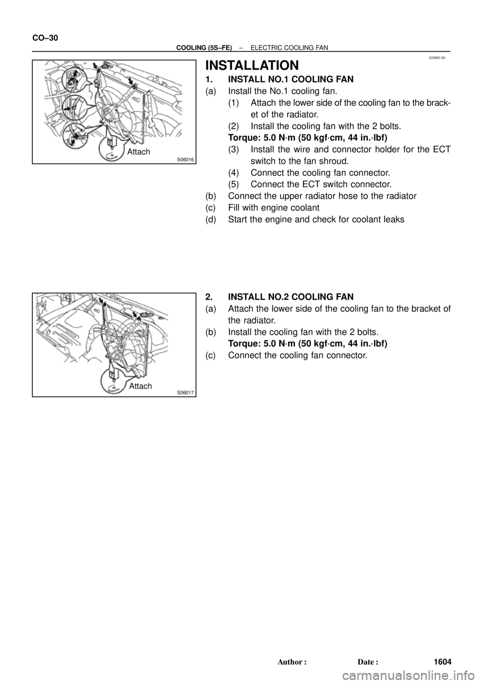
S06016Attach
S06017Attach CO±30
± COOLING (5S±FE)ELECTRIC COOLING FAN
1604 Author�: Date�:
INSTALLATION
1. INSTALL NO.1 COOLING FAN
(a) Install the No.1 cooling fan.
(1) Attach the lower side of the cooling fan to the brack-
et of the radiator.
(2) Install the cooling fan with the 2 bolts.
Torque: 5.0 N´m (50 kgf´cm, 44 in.´lbf)
(3) Install the wire and connector holder for the ECT
switch to the fan shroud.
(4) Connect the cooling fan connector.
(5) Connect the ECT switch connector.
(b) Connect the upper radiator hose to the radiator
(c) Fill with engine coolant
(d) Start the engine and check for coolant leaks
2. INSTALL NO.2 COOLING FAN
(a) Attach the lower side of the cooling fan to the bracket of
the radiator.
(b) Install the cooling fan with the 2 bolts.
Torque: 5.0 N´m (50 kgf´cm, 44 in.´lbf)
(c) Connect the cooling fan connector.
Page 1176 of 4592
COOLANT
1610 Author�: Date�:
REPLACEMENT
1. DRAIN ENGINE COOLANT
(a) Remove the radiator cap from the water outlet.
CAUTION:
To avoid t")
CO03C±04
Z18835
Drain Plug
Drain Plug CO±2
± COOLING (1MZ±FE)COOLANT
1610 Author�: Date�:
REPLACEMENT
1. DRAIN ENGINE COOLANT
(a) Remove the radiator cap from the water outlet.
CAUTION:
To avoid the danger of being burned, do not remove the ra-
diator cap while the engine and radiator are still hot, as fluid
and steam can be blown out under pressure.
(b) Loosen the radiator drain plug and engine drain plugs,
and drain the coolant.
(c) Close the drain plugs.
Torque:
RH engine drain plug on EGR cooler:
7 N´m (70 kgf´cm, 61 in.´lbf)
LH engine drain plug on union:
13 N´m (130 kgf´cm, 9 ft´lbf)
2. FILL ENGINE COOLANT
(a) Slowly fill the system with coolant.
�Use of improper coolants may damage engine cool-
ing system.
�Use ºToyota Long life Coolantº or equivalent and
mix it with plan water according to the manufactur-
er's directions.
�Using of coolant which includes more than 50 %
(freezing protection down to ±35°C (±31°F) or 60 %
(freezing protection down to ±50°C (±58°F)) of eth-
ylene±glycol is recommended but not more than 70
%.
NOTICE:
�Do not use an alcohol type coolant or plain water
alone.
�The coolant should be mixed with plain water (prefer-
ably demineralized water or distilled water).
Capacity: 9.2 liters (9.7 US qts, 8.1 lmp. qts)
(b) Install the radiator cap.
(c) Start the engine, and bleed the cooling system.
(d) If necessary, refill coolant into the reservoir up to the
ºFULLº line.
3. CHECK ENGINE COOLANT FOR LEAKS
4. CHECK ENGINE COOLANT SPECIFIC GRAVITY
CORRECTLY
Page 1177 of 4592
CO03D±04
A06654
RH Fender Apron Seal
Generator Drive BeltEngine Moving
Control Rod
RH Engine Mounting Stay
No.2 RH Engine
Mounting Bracket
Ground Strap PS Pump Drive Belt
Engine Coolant Reservoir Hose
: Specified torqueNo.2 RH Engine
Mounting Stay (M/T)
64 (650, 47)
32 (320, 23)
64 (650, 47)
N´m (kgf´cm, ft´lbf)
± COOLING (1MZ±FE)WATER PUMP
CO±3
1611 Author�: Date�:
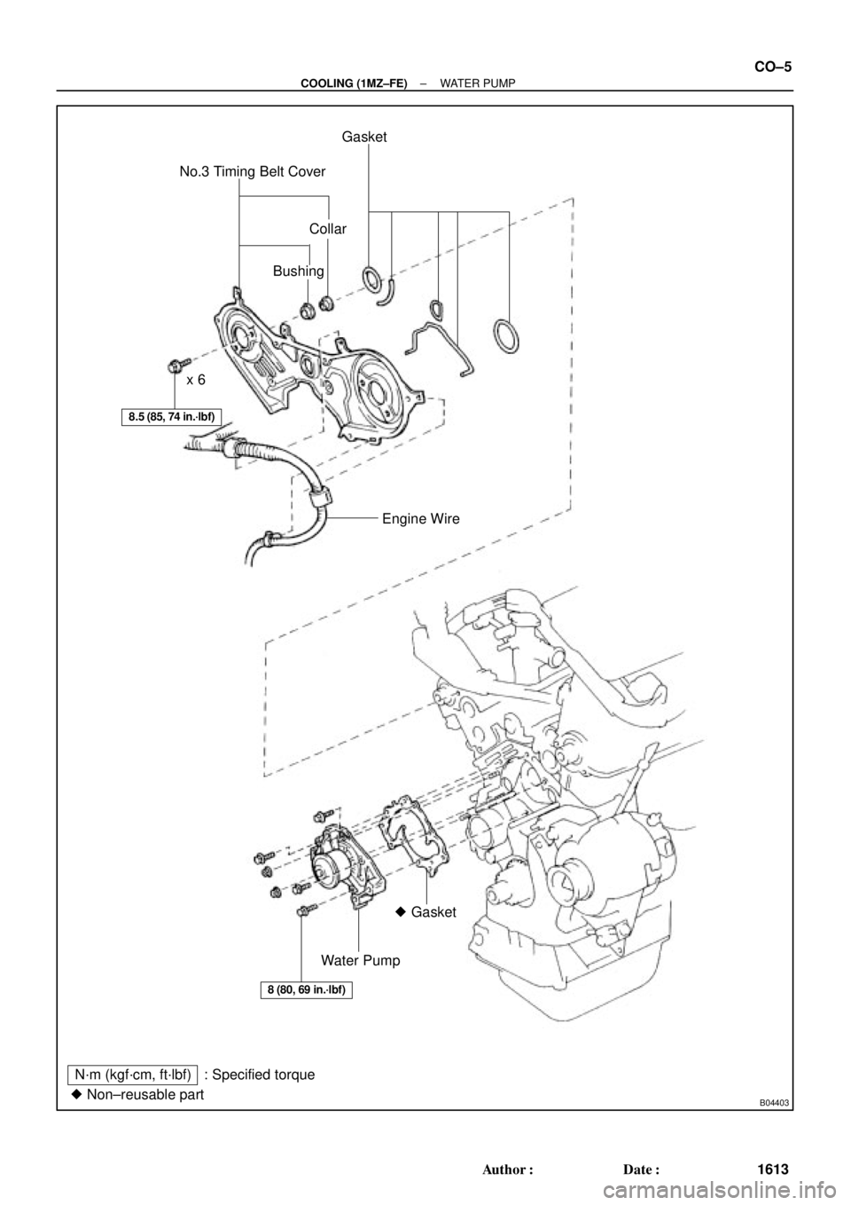
WATER PUMP
COMPONENTS
Page 1178 of 4592
B06388
No.2 Timing Belt CoverTiming Belt
Gasket
Timing Belt Guide
No.2 Generator
Bracket RH Engine Mounting Bracket
Crankshaft
PulleyGasket
Engine Wire Protector
RH Camshaft Timing PulleyNo.2 Idler Pulley
Dust Boot
Timing Belt Tensioner
� Non±reusable part
*For use with SSTNo.1 Timing Belt Cover
LH Camshaft
Timing Pulley
N´m (kgf´cm, ft´lbf) : Specified torque
28 (290, 21)
215 (2,200, 159)
125 (1,300, 94)*88 (900, 65)
43 (440, 32)
27 (280, 20)
125 (1,300, 94)
CO±4
± COOLING (1MZ±FE)WATER PUMP
1612 Author�: Date�:
Page 1179 of 4592
B04403� Non±reusable partNo.3 Timing Belt CoverGasket
Collar
Bushing
Water Pump� Gasket Engine Wire x 6
N´m (kgf´cm, ft´lbf) : Specified torque
8.5 (85, 74 in.´lbf)
8 (80, 69 in.´lbf)
± COOLING (1MZ±FE)WATER PUMP
CO±5
1613 Author�: Date�: