Page 2311 of 4592

SYSTEM DESCRIPTION
The ECM uses the signals from the")
Q07745
Drain
Drain Line
Pressure
Q07746
± DIAGNOSTICSAUTOMATIC TRANSAXLE
DI±159
DTC P0770 Shift Solenoid E Malfunction
(Shift Solenoid Valve SL)
SYSTEM DESCRIPTION
The ECM uses the signals from the throttle position sensor, air±
flow meter and crankshaft position sensor to monitor the en-
gagement condition of the lock±up clutch.
Then the ECM compares the engagement condition of the
lock±up clutch with the lock±up schedule in the ECM memory
to detect mechanical trouble of the shift solenoid valve SL,
valve body, torque converter clutch or automatic transaxle
(clutch, brake or gear etc.).
DTC No.DTC Detecting ConditionTrouble Area
P0770
�Lock±up does not occur when driving in the lock±up range
(normal driving at 80 km/h [50 mph]), or lock±up remains ON
in the lock±up OFF range.
(2 trip detection logic)
�When lock±up is ON, clutch or brake slips or gear is broken.�Shift solenoid valve SL is stuck open or closed
�Valve body blocked up or stuck
�Lock±up clutch
�Automatic transaxle (clutch, brake or gear etc.)
INSPECTION PROCEDURE
1 Check solenoid valve SL operation.
PREPARATION:
(a) Remove the oil pan.
(b) Remove the shift solenoid valve SL.
CHECK:
(a) By applying 490 kPa (5 kgf/cm2, 71 psi) of compressed
air, check that the solenoid valve does not leak air.
(b) When battery positive voltage is supplied to the shift sole-
noid valve, check that the solenoid valve opens.
OK:
(a) Solenoid valve does not leak air.
(b) Solenoid valve opens.
NG Replace the solenoid valve SL.
OK
DI034±05
Page 2312 of 4592
DI±160
± DIAGNOSTICSAUTOMATIC TRANSAXLE
2 Check valve body (See page DI±148).
NG Repair or replace the valve body.
OK
3 Check the torque converter clutch (See Pub. No. RM654U on page AX±26).
NG Replace the torque converter clutch.
OK
Repair or replace the transaxle.
Page 2521 of 4592
EC03D±05
B06534
Vapor Pressure Sensor
ConnectorVSV for Vapor Pressure Sensor
ConnectorEVAP Line Hose
Vent Line Hose
Air Inlet Line Hose
Purge Line Hose
Air Drain Hose
39.2 (400, 29)
N´m (kgf´cm, ft´lbf) : Specified torqueCharcoal Canister
Assembly
Charcoal Canister
Vapor Pressure Sensor
Mounting Bolt
± EMISSION CONTROL (5S±FE)EVAPORATIVE EMISSION (EVAP) CONTROL SYSTEM
EC±5
1403 Author�: Date�:
EVAPORATIVE EMISSION (EVAP) CONTROL SYSTEM
COMPONENTS
Page 2530 of 4592
S05559
EC±14
± EMISSION CONTROL (5S±FE)EXHAUST GAS RECIRCULATION (EGR) SYSTEM
1412 Author�: Date�:
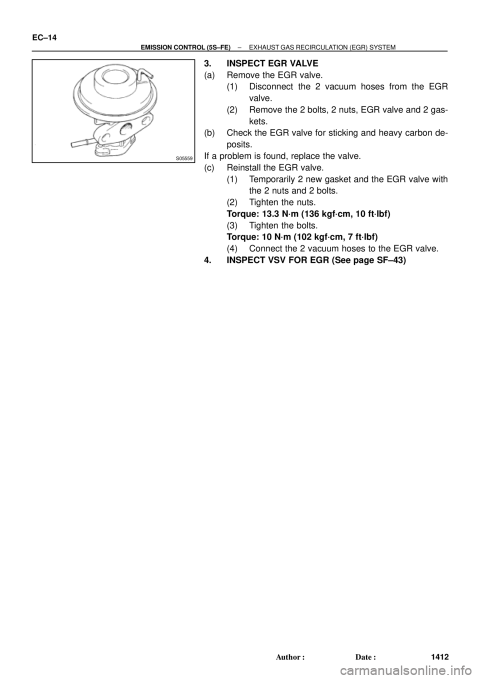
3. INSPECT EGR VALVE
(a) Remove the EGR valve.
(1) Disconnect the 2 vacuum hoses from the EGR
valve.
(2) Remove the 2 bolts, 2 nuts, EGR valve and 2 gas-
kets.
(b) Check the EGR valve for sticking and heavy carbon de-
posits.
If a problem is found, replace the valve.
(c) Reinstall the EGR valve.
(1) Temporarily 2 new gasket and the EGR valve with
the 2 nuts and 2 bolts.
(2) Tighten the nuts.
Torque: 13.3 N´m (136 kgf´cm, 10 ft´lbf)
(3) Tighten the bolts.
Torque: 10 N´m (102 kgf´cm, 7 ft´lbf)
(4) Connect the 2 vacuum hoses to the EGR valve.
4. INSPECT VSV FOR EGR (See page SF±43)
Page 2532 of 4592
EC03I±04
B06537
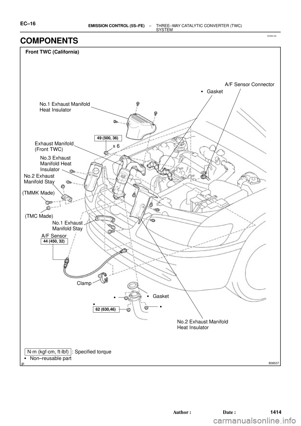
Front TWC (California)
Exhaust Manifold
(Front TWC)
No.3 Exhaust
Manifold Heat
Insulator
No.2 Exhaust
Manifold Stay
A/F Sensor� GasketA/F Sensor Connector
� Gasket Clampx 6
�
�
N´m (kgf´cm, ft´lbf)
� Non±reusable part
49 (500, 36)
44 (450, 32)
62 (630,46)
: Specified torque
No.1 Exhaust
Manifold Stay
�
No.1 Exhaust Manifold
Heat Insulator
No.2 Exhaust Manifold
Heat Insulator
(TMC Made)
(TMMK Made)
EC±16± EMISSION CONTROL (5S±FE)THREE±WAY CATALYTIC CONVERTER (TWC)
SYSTEM
1414 Author�: Date�:
COMPONENTS
Page 2533 of 4592
B06538
N´m (kgf´cm, ft´lbf)
� Non±reusable part
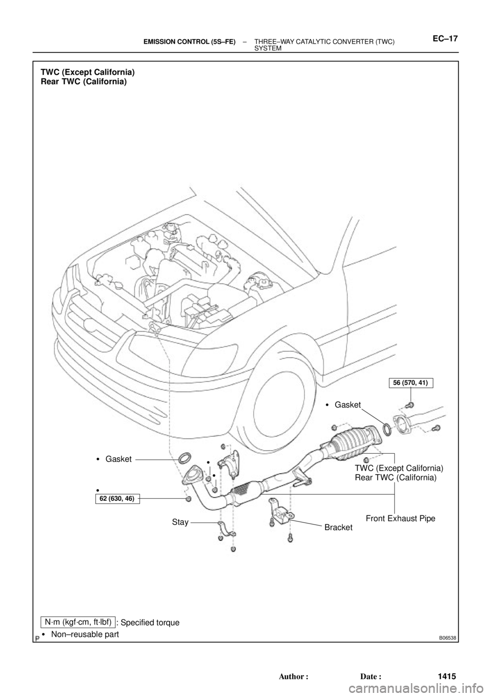
TWC (Except California)
Rear TWC (California)
� Gasket
BracketTWC (Except California)
Rear TWC (California)
Front Exhaust Pipe � Gasket
Stay
62 (630, 46)
56 (570, 41)
: Specified torque�
�
�
± EMISSION CONTROL (5S±FE)THREE±WAY CATALYTIC CONVERTER (TWC)
SYSTEMEC±17
1415 Author�: Date�:
Page 2538 of 4592
EC0AU±01
B01507
Vapor Pressure Sensor
ConnectorVapor Pressure SensorVSV Connector for Vapor
Pressure SensorEVAP Line Hose
Vent Line Hose
Air Inlet Line Hose
Purge Line Hose
Air Drain Hose
VSV for Vapor Pressure Sensor
39.2 (400, 29)
N´m (kgf´cm, ft´lbf) : Specified torqueCharcoal Canister
± EMISSION CONTROL (1MZ±FE)EVAPORATIVE EMISSION (EVAP) CONTROL SYSTEM
EC±5
1420 Author�: Date�:
EVAPORATIVE EMISSION (EVAP) CONTROL SYSTEM
COMPONENTS
Page 2545 of 4592
 EGLS(+)
S05452
S05455
(1)
(2)
(3)
EC±12
± EMISSION CONTROL (1MZ±FE)EXHAUST GAS RECIRCULATION (EGR) SYSTEM
1427 Author�: Date�:
(4) Connect a voltmeter to terminals EGLS an")
B01482
Disconnect
E2(±) EGLS(+)
S05452
S05455
(1)
(2)
(3)
EC±12
± EMISSION CONTROL (1MZ±FE)EXHAUST GAS RECIRCULATION (EGR) SYSTEM
1427 Author�: Date�:
(4) Connect a voltmeter to terminals EGLS and E2 of
the ECM, and measure the power outlet voltage un-
der the following conditions:
�Using a MITYVAC (Hand±Held Vacuum
Pump), apply a vacuum (17.3 kPa, 130
mmHg, 5.1 in.Hg) to the EGR valve.
Voltage: 3.2 ± 5.1 V
�Release the vacuum from the EGR valve.
Voltage: 0.4 ± 1.6 V
If the voltage is not as specified, replace the EGR valve position
sensor.
(5) Reconnect the vacuum hose to the EGR valve.
3. REMOVE EGR POSITION SENSOR
Remove the 3 nuts and EGR valve position sensor from the
EGR valve.
Torque: 2 N´m (20 kgf´cm, 17 in.´lbf)
4. REINSTALL EGR POSITION SENSOR
Installation is the reverse order of removal.
5. REMOVE EGR VALVE
(a) Remove the EGR pipe.
�Remove the 4 nuts, EGR pipe and 2 gaskets.
HINT:
At the time of installation, please refer to the following items.
Install 2 new gaskets.
Torque: 12 N´m (120 kgf´cm, 9 ft´lbf)
(b) Disconnect the EGR gas temperature sensor connector
and clamp.
(c) Remove the EGR valve.
(1) Disconnect the EVAP hose from the EGR valve
hook.
(2) Disconnect the vacuum hose from the EGR valve.
(3) Disconnect the EGR valve position sensor connec-
tor.
(d) Remove the 3 nuts, EGR valve and gasket.
HINT:
At the time of installation, please refer to the following items.
Install a new gasket.
Torque: 12 N´m (120 kgf´cm, 9 ft´lbf)
(e) Remove the EGR gas temperature sensor.
Torque: 20 N´m (200 kgf´cm, 14 ft´lbf)
.
NG Repair or replace the valve body.
OK
3 Check the torque converter clutch (See Pub. No. RM654U on page AX±26).
NG Re")

N´m (kgf´cm, ft")