Page 2578 of 4592

Length = 230 mm (9.06 in.)
± ENGINE MECHANICAL (5S±FE)TIMING BELT
EM±27
1199 Author�: Date�:
(b) Slowly turn the crankshaft")
S05587
Turn
S05598
S05586
Turn
S05585
S01710
Length = 735 mm (28.94 in.)
Length = 230 mm (9.06 in.)
± ENGINE MECHANICAL (5S±FE)TIMING BELT
EM±27
1199 Author�: Date�:
(b) Slowly turn the crankshaft pulley 2 revolutions TDC to
TDC.
NOTICE:
Always turn the crankshaft pulley clockwise.
(c) Check that each pulley aligns with the timing marks as
shown in the illustration.
If the timing marks do not align, remove the timing belt and rein-
stall it.
(d) Slowly turn the crankshaft pulley 1 and 7/8 revolutions,
and align its groove with the mark at 45° BTDC (for No.1
cylinder) of the No.1 timing belt cover.
NOTICE:
Always turn the crankshaft pulley clockwise.
(e) Tighten the mounting bolt of the No.1 idler pulley.
Torque: 42 N´m (425 kgf´cm, 31 ft´lbf)
13. INSTALL NO.2 TIMING BELT COVER
(a) Check that the timing belt cover gaskets have no cracks
or peeling, etc.
If the gasket has cracks or peeling, etc., replace it using these
steps:
(1) Using a screwdriver and gasket scraper, remove all
the old gasket material.
(2) Thoroughly clean all components to remove all the
loose material.
Page 2579 of 4592
TIMING BELT
1200 Author�: Date�:
(3) Remove the backing paper from a new gasket and
install the gasket evenly to the part of the timing")
S05596
S05296
S05249
S05609
EM±28
± ENGINE MECHANICAL (5S±FE)TIMING BELT
1200 Author�: Date�:
(3) Remove the backing paper from a new gasket and
install the gasket evenly to the part of the timing belt
cover shaded black in the illustration.
(4) After installing the gasket, press down on it so that
the adhesive firmly sticks to the timing belt cover.
(b) Install the belt cover with the 4 bolts.
(c) Install the engine wire clamp.
14. INSTALL SPARK PLUGS
(a) Install the 4 spark plugs.
(b) Connect the 4 high±tension cords to the spark plugs.
(c) Install the 4 high±tension cords to the clamps on the cylin-
der head cover.
15. INSTALL NO.2 RH ENGINE MOUNTING BRACKET
(a) Install the mounting bracket with the 3 bolts.
(b) Alternately tighten the 3 bolts in several passes.
Torque: 52 N´m (530 kgf´cm, 38 ft´lbf)
16. INSTALL ENGINE MOVING CONTROL ROD
(a) Temporarily install the control rod with the 3 bolt.
(b) Alternately tighten the 3 bolts in several passes.
Torque: 64 N´m (650 kgf´cm, 47 ft´lbf)
17. CONNECT GROUND STRAP CONNECTOR
18. INSTALL PS PUMP DRIVE BELT
Install the drive belt with the 2 bolts.
19. INSTALL RH FRONT FENDER APRON SEAL
20. INSTALL RH FRONT WHEEL
21. INSTALL GENERATOR (See page CH±16)
Page 2580 of 4592
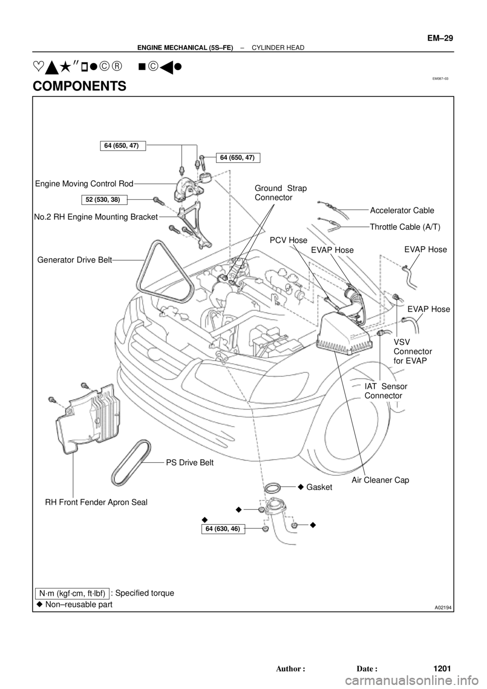
EM087±03
A02194
Engine Moving Control Rod
No.2 RH Engine Mounting Bracket
Generator Drive Belt
RH Front Fender Apron SealPS Drive Belt
� GasketAir Cleaner Cap
IAT Sensor
ConnectorEVAP Hose
VSV
Connector
for EVAPEVAP Hose
EVAP Hose
PCV HoseThrottle Cable (A/T)Accelerator Cable Ground Strap
Connector
N´m (kgf´cm, ft´lbf)
64 (650, 47)
64 (650, 47)
52 (530, 38)
64 (630, 46)� �
�
� Non±reusable part: Specified torque
± ENGINE MECHANICAL (5S±FE)CYLINDER HEAD
EM±29
1201 Author�: Date�:
���� ��
� ����
COMPONENTS
Page 2581 of 4592

A01562
Generator Wire
Generator
Connector
GeneratorWire Clamp
Wire
Clamp
ECT Sender
Gauge ConnectorThrottle BodyThrottle Position
Sensor ConnectorIgnition Coil Connector
IAC Valve
Connector
Heater Water Hose
Radiator Hose ECT Sensor
Connector
Water Outlet
Noise Filter Connector
Oil Pressure Switch Connector
Ignition Coil and No.2 Intake
Manifold Assembly
(with High±Tension Cord)
A/F Sensor Connector (California) or
Heated Oxygen Sensor (Bank 1 Sensor 1)
Connector (Except California)
(TMMK Made) � Gasket� Gasket � Gasket
(TMC Made)No.1 Exhaust
Manifold Stay
No.2 Exhaust
Manifold Stay No.1 Exhaust
Manifold Heat
Insulator
Exhaust Manifold,
No.2 and No.3
Exhaust Manifold
Heat Insulator
Assembly
� Non±reusable partExcept California
19 (195, 14)
49 (500, 36)
49 (500, 36)
: Specified torqueN´m (kgf´cm, ft´lbf)x 6
Exhaust Manifold,
No.2 and no.3
Exhaust Manifold
Heat Insulator
Assenbly
(California)
No.1 Exhaust
Manifold Heat
Insulator (California) (TMMK Made)
(TMC Made)
EM±30
± ENGINE MECHANICAL (5S±FE)CYLINDER HEAD
1202 Author�: Date�:
Page 2582 of 4592
A07358
Ground Wire
MAP Sensor
Vacuum Hose
Brake Booster
Vacuum Hose
Intake
Manifold
Air Hose for Air Assist System (California)
Intake Manifold
Stay
Injector
(Except California)
Knock Sensor 1
ConnectorPCV HoseVSV Connector
for EGR
VSV for EGREGR Valve and Vacuum
Modulator
Fuel Inlet Hose
Fuel Pulsation Damper
� O±Ring
Injector
(California)Injector
Connector Spacer
Insulator
N´m (kgf´cm, ft´lbf)
� Non±reusable part
� Gasket
� Insulator� Grommet
� O±Ring � Gasket� Gasket
* For use with SST
19 (195, 14)
34 (350, 25)* 29 (300, 21)
: Specified torque
x 6
Engine Wire
13 (130, 9)
Spacer
± ENGINE MECHANICAL (5S±FE)CYLINDER HEAD
EM±31
1203 Author�: Date�:
Page 2583 of 4592

A07368
Spark Plug
Grommet
Cylinder Head Cover
Gasket
Camshaft Bearing Cap
� Camshaft Oil Seal
Camshaft Timing Pulley
Snap Ring
Wave Washer
Camshaft Position Sensor Connector
Camshaft Position Sensor Assembly
Wire Clamp
No. 3 Timing Belt Cover
No.2 Timing Belt Cover� Oil Seal
Valve Guide
Bushing
Cylinder
Head
Gasket Adjusting Shim
Valve Lifter
Keeper
Spring Retainer
Valve Spring
Spring Seat
Valve
LH Engine
Hanger
Semi±Circular
Plug
Oil Pressure
Switch
Camshaft Gear Spring
Camshaft Sub±Gear
Semi±Circular
Plug
Tension Spring
No.1 Idler Pulley
*
1
GasketTiming Belt
Cylinder Head Intake
CamshaftExhaust
Camshaft
Wire
Clamp
Wire
Clamp
Generator Bracket and
RH Engine Hanger
Assembly
N´m (kgf´cm, ft´lbf)
*
2 For use with SST
� Non±reusable part
18 (180, 13)
44 (450, 33)
19 (190, 14)
*
237 (380, 27)1st 49 (500, 36)
2nd Turn 90°
42 (425, 31)
x 10�
�
: Specified torque
See page EM±53
*1
Replace only if damaged
54 (550, 40)
EM±32
± ENGINE MECHANICAL (5S±FE)CYLINDER HEAD
1204 Author�: Date�:
Page 2603 of 4592
CYLINDER HEAD
1224 Author�: Date�:
REASSEMBLY
HINT:
�Thoroughly clean all parts to be assemb")
EM0YM±01
P03274
SST
Z02903
Intake Exhaust
Gray
Black
P03265
SST
P03276
EM±52
± ENGINE MECHANICAL (5S±FE)CYLINDER HEAD
1224 Author�: Date�:
REASSEMBLY
HINT:
�Thoroughly clean all parts to be assembled.
�Before installing the parts, apply new engine oil to all slid-
ing and rotating surfaces.
�Replace all gaskets and oil seals with new ones.
1. INSTALL VALVES
(a) Using SST, push in a new oil seal.
SST 09201±41020
HINT:
The intake valve oil seal is gray and the exhaust valve oil seal
is black.
(b) Install the valve, spring seat, valve spring and spring re-
tainer.
(c) Using SST, compress the valve spring and place the 2
keepers around the valve stem.
SST 09202±70020 (09202±00010)
(d) Using a plastic±faced hammer, lightly tap the valve stem
tip to assure a proper fit.
2. INSTALL VALVE LIFTERS AND SHIMS
(a) Install the valve lifter and shim.
(b) Check that the valve lifter rotates smoothly by hand.
3. INSTALL CAMSHAFT POSITION SENSOR AS-
SEMBLY
Install the sensor assembly with the bolt.
Torque: 9.5 N´m (97 kgf´cm, 84 in.´lbf)
Page 2604 of 4592
CYLINDER HEAD
EM±53
1225 Author�: Date�:
INSTALLATION
1. PLACE CYLINDER HEAD ON CYLIND")
EM08D±04
A07355
Z02750
1
10 24 6 839
7 5
S01690
90°
Front
Painted
Mark90°
P03279
± ENGINE MECHANICAL (5S±FE)CYLINDER HEAD
EM±53
1225 Author�: Date�:
INSTALLATION
1. PLACE CYLINDER HEAD ON CYLINDER BLOCK
(a) Place a new cylinder head gasket on the cylinder block.
NOTICE:
Be careful of the installation direction.
(b) Place the cylinder head on the cylinder head gasket.
2. INSTALL CYLINDER HEAD BOLTS
HINT:
�The cylinder head bolts are tightened in 2 progressive
steps (steps (b) and (d)).
�If any cylinder head bolt is broken or deformed, replace
it.
(a) Apply a light coat of engine oil on the threads and under
the heads of the cylinder head bolts.
(b) Install and uniformly tighten the 10 cylinder head bolts
and plate washers in several passes, in the sequence
shown.
Torque: 49 N´m (500 kgf´cm, 36 ft´lbf)
If any one of the cylinder head bolts does not meet the torque
specification, replace the cylinder head bolt.
(c) Mark the front of the cylinder head bolt head with paint.
(d) Retighten the cylinder head bolts 90° in the numerical or-
der shown.
(e) Check that the painted mark is now at a 90° angle to the
front.
(f) Install the 2 bolts holding the water bypass pipe to the cyl-
inder head.
Torque: 19 N´m (195 kgf´cm, 14 ft´lbf)
(g) Connect the camshaft position sensor connector.
3. INSTALL SPARK PLUG TUBES
(a) Clean the cylinder head tube holes of any residual adhe-
sive, oil or foreign particles. Remove any oil with kerosene
or gasoline.
(b) Screw the threads of the spark plug tube coated with
adhesive into the cylinder head.
(c) Using the spark plug tube nut and a 30 mm socket
wrench, tighten the spark plug tubes.
Torque: 49 N´m (500 kgf´cm, 36 ft´lbf)

Intake Manifold
Stay
Injector
(Except California)
Knock Sensor 1
Connec")