Page 2548 of 4592
EC021±04
B06395
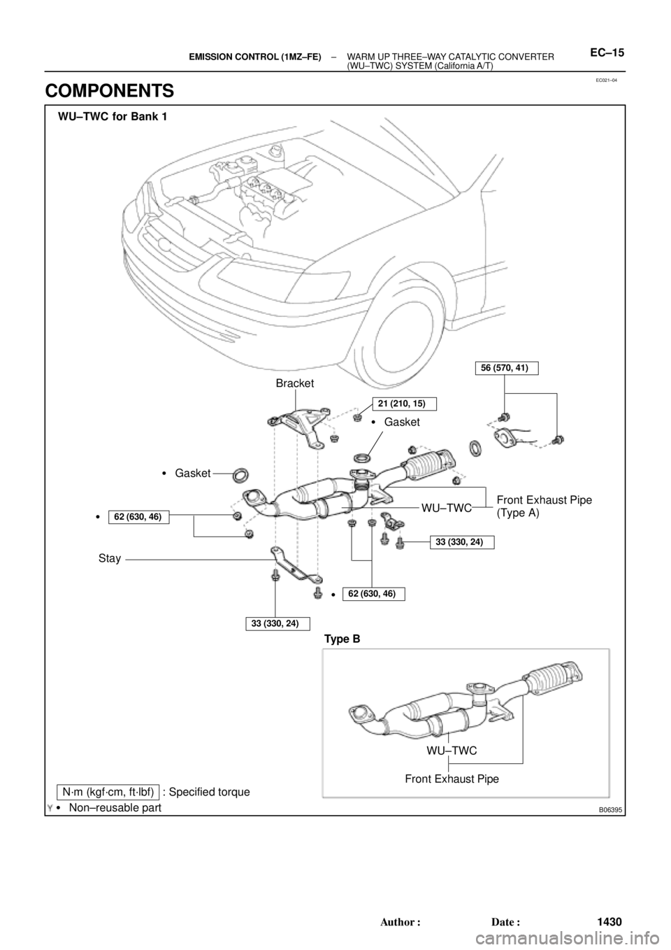
N´m (kgf´cm, ft´lbf) : Specified torque
� Non±reusable partBracket
� Gasket
Stay
62 (630, 46)
33 (330, 24)
56 (570, 41)
WU±TWCFront Exhaust Pipe
(Type A) � Gasket
�
62 (630, 46)
33 (330, 24)
WU±TWC for Bank 1
�
21 (210, 15)
Front Exhaust Pipe
WU±TWC
Type B
± EMISSION CONTROL (1MZ±FE)WARM UP THREE±WAY CATALYTIC CONVERTER
(WU±TWC) SYSTEM (California A/T)EC±15
1430 Author�: Date�:
COMPONENTS
Page 2549 of 4592
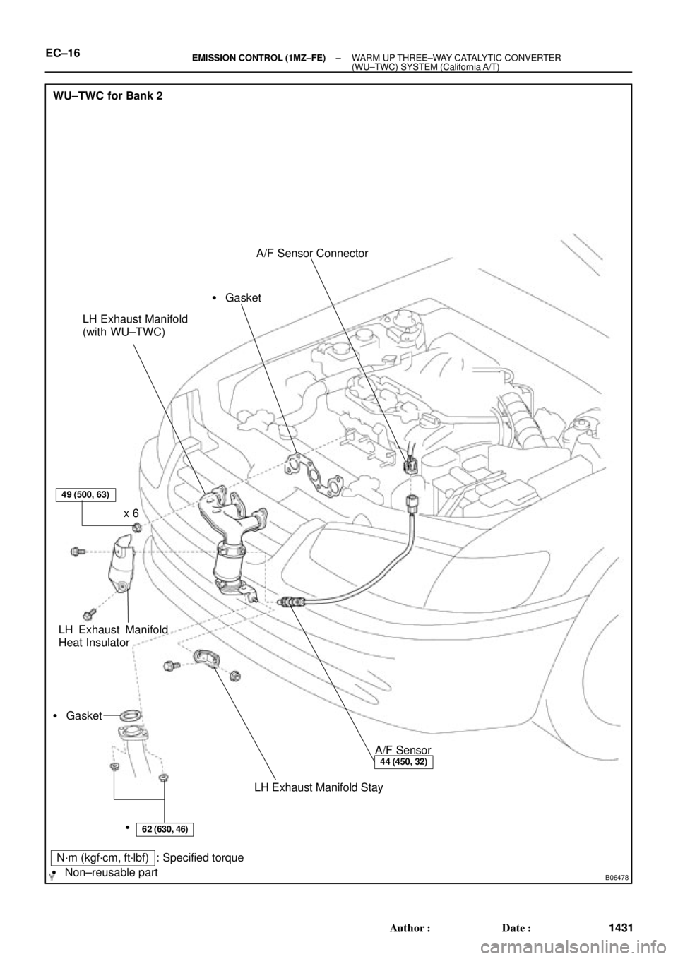
B06478
WU±TWC for Bank 2
LH Exhaust Manifold
(with WU±TWC)
LH Exhaust Manifold
Heat InsulatorA/F Sensor Connector
A/F Sensor
LH Exhaust Manifold Stay � Gasket� Gasket
49 (500, 63)
62 (630, 46)
44 (450, 32)
x 6
�
N´m (kgf´cm, ft´lbf) : Specified torque
� Non±reusable part
EC±16± EMISSION CONTROL (1MZ±FE)WARM UP THREE±WAY CATALYTIC CONVERTER
(WU±TWC) SYSTEM (California A/T)
1431 Author�: Date�:
Page 2551 of 4592
EC023±04
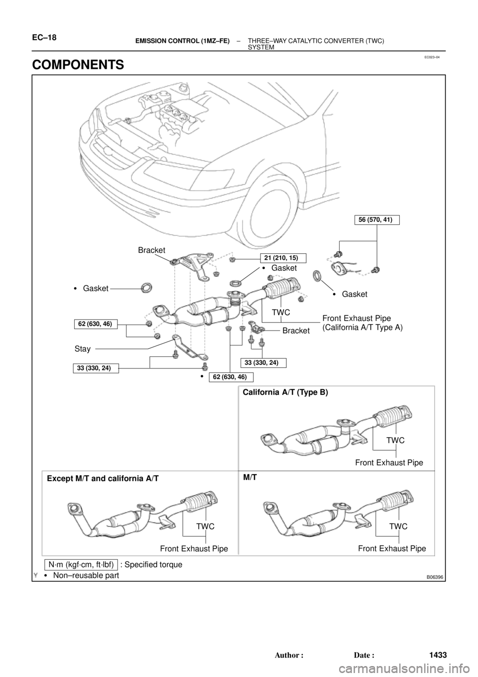
B06396
Except M/T and california A/TCalifornia A/T (Type B)
M/T
TWC
Front Exhaust Pipe
N´m (kgf´cm, ft´lbf) : Specified torque
� Non±reusable part
TWC
Front Exhaust Pipe
Bracket
� Gasket
Stay
62 (630, 46)
56 (570, 41)
TWC
Front Exhaust Pipe
(California A/T Type A)� Gasket � Gasket
�
62 (630, 46)
33 (330, 24)33 (330, 24)
Bracket
TWC
Front Exhaust Pipe
21 (210, 15)
EC±18± EMISSION CONTROL (1MZ±FE)THREE±WAY CATALYTIC CONVERTER (TWC)
SYSTEM
1433 Author�: Date�:
COMPONENTS
Page 2564 of 4592
BALANCE SHAFT BACKLASH
EM±13
1185 Author�: Date�:
(p) Turn the crankshaft clockw")
Z19415
No.1 Balance
Shaft
Mark B
Mark A
No.2 Housing
Z19408
2
46 153
Z19409
1
35 Pull
264
± ENGINE MECHANICAL (5S±FE)BALANCE SHAFT BACKLASH
EM±13
1185 Author�: Date�:
(p) Turn the crankshaft clockwise again to align the groove
of the No.2 housing with punch mark B.
(q) Set the dial indicator. (See step (e))
(r) Measure the backlash. (See step (f))
Standard backlash (at punch mark B):
0.025 ± 0.085 mm (0.0010 ± 0.0033 in.)
(s) Remove the dial indicator.
If even one of the 4 points measured above exceeds the back-
lash specification, adjust the backlash with new spacers.
NOTICE:
Use the same size spacers for both the left and right sides.
HINT:
�Varying the spacer thickness by 0.02 mm (0.0008 in.)
changes the backlash by about 0.014 mm (0.0006 in.).
�If the backlash is greater than the permitted maximum,
select a thinner shim.
�If the backlash is less than the specification, select a thick-
er shim.
3. REPLACE NEW SPACERS
(a) Uniformly loosen the 6 bolts in the sequence shown.
(b) Replace the spacers with new ones.
4. TIGHTEN BALANCE SHAFT ASSEMBLY
While pulling the center part of the engine balancer in the direc-
tion of the arrow, uniformly tighten the 6 bolts in several passes,
in the sequence shown.
Torque: 49 N´m (500 kgf´cm, 36 ft´lbf)
5. INSPECT AND ADJUST BACKLASH OF CRANK-
SHAFT GEAR AND NO.1 BALANCE SHAFT GEAR
(See step 2)
6. REINSTALL OIL STRAINER AND OIL PAN
(See page LU±13)
Page 2566 of 4592
EM083±03
S05284
Engine Moving Control Rod
No.2 RH Engine Mounting Bracket
Generator Drive Belt
RH Front Fender Apron SealPS Pump Drive BeltGround Strap Connector
N´m (kgf´cm, ft´lbf)
52 (530, 38)64 (650, 47)
64 (650, 47)
: Specified torque
± ENGINE MECHANICAL (5S±FE)TIMING BELT
EM±15
1187 Author�: Date�:
TIMING BELT
COMPONENTS
Page 2567 of 4592
S05937
No.2 Timing Belt
Cover
No.1 Timing Belt
Cover
Tension Spring Crankshaft
Pulley
Camshaft Timing Pulley
No.1 Idler Pulley
No.2 Idler Pulley
Oil Pump Pulley
Crankshaft Timing Pulley Wire ClampWire ClampWire ClampSpark Plug High±Tension CordTiming Belt Guide Timing Belt
*
1 Gasket Wire
ClampGenerator Wire
Generator Connector
Generator
Wire
Clamp
N´m (kgf´cm, ft´lbf)
*
2 For use with SST
42 (425, 31)
42 (425, 31)
24 (245, 18)18 (180, 13) 108 (1,100, 80)
54 (550, 40)
*
2
37 (380, 27)
: Specified torque*
1 Gasket
*
1
Replace only if damaged EM±16
± ENGINE MECHANICAL (5S±FE)TIMING BELT
1188 Author�: Date�:
Page 2574 of 4592
TIMING BELT
EM±23
1195 Author�: Date�:
INSTALLATION
1. INSTALL OIL PUMP PULLEY
(")
EM086±04
S05576
SST
S05577
Angle
Sensor
Inward
S05571
35 mm
S05616
42 mm
S05926
Pry
Move
± ENGINE MECHANICAL (5S±FE)TIMING BELT
EM±23
1195 Author�: Date�:
INSTALLATION
1. INSTALL OIL PUMP PULLEY
(a) Align the cutouts of the pulley and shaft, and slide on the
pulley.
(b) Using SST, install the pulley nut.
SST 09960±10010 (09962±01000, 09963±00500)
Torque: 24 N´m (245 kgf´cm, 18 ft´lbf)
2. INSTALL CRANKSHAFT TIMING PULLEY
(a) Align the timing pulley set key with the key groove of the
pulley.
(b) Slide on the timing pulley, facing the angle sensor inward.
NOTICE:
Do not scratch the angle sensor of the timing pulley.
3. INSTALL NO.2 IDLER PULLEY
(a) Install the pulley with the bolt.
Torque: 42 N´m (425 kgf´cm, 31 ft´lbf)
HINT:
Use the 35 mm (1.38 in.) long bolt.
(b) Check that the idler pulley moves smoothly.
4. TEMPORARILY INSTALL NO.1 IDLER PULLEY AND
TENSION SPRING
(a) Align the bracket pin hole with the pivot pin.
(b) Install the pulley with the bolt. Do not tighten the bolt yet.
HINT:
Use the 42 mm (1.65 in.) long bolt.
(c) Install the tension spring.
(d) Pry the pulley toward the left as far as it will go, and tighten
the bolt.
(e) Check that the idler pulley moves smoothly.
Page 2576 of 4592
TIMING BELT
EM±25
1197 Author�: Date�:
(b) Install the timing belt cover with the 4 bolts.
(c) Install the")
A02591
S05588
SSTSST
S05592
SST
SST
Fulcrum
Length
S05587
Turn
± ENGINE MECHANICAL (5S±FE)TIMING BELT
EM±25
1197 Author�: Date�:
(b) Install the timing belt cover with the 4 bolts.
(c) Install the clamp of the crankshaft position sensor wire to
the timing belt cover.
(d) Install the crankshaft position sensor wire to the clamp on
the timing belt cover.
8. INSTALL CRANKSHAFT PULLEY
(a) Align the pulley set key with the key groove of the pulley,
and slide on the pulley.
(b) Using SST (and bolt), install the pulley bolt.
SST 09213±54015 (91651±60855),09330±00021
Torque: 108 N´m (1,100 kgf´cm, 80 ft´lbf)
HINT:
Either of 2 types of pulley may be used, each with its own bolt
size, type A (91651±60855) and type B
(part No. 91121±40665).
9. INSTALL CAMSHAFT TIMING PULLEY
(a) Align the camshaft knock pin with the knock pin groove of
the pulley, and slide on the timing pulley.
(b) Using SST, install the pulley bolt.
SST 09249±63010, 09960±10010 (09962±01000,
09963±01000)
Torque:
54 N´m (550 kgf´cm, 40 ft´lbf)
37 N´m (380 kgf´cm, 27 ft´lbf) for use with SST
HINT:
Use a torque wrench with a fulcrum length of 340 mm (13.39
in.).
10. SET NO.1 CYLINDER TO TDC/COMPRESSION
(a) Turn the crankshaft pulley, and align its groove with timing
mark º0º of the No.1 timing belt cover.

52 (530, 38)6")
