Page 2636 of 4592
A07353
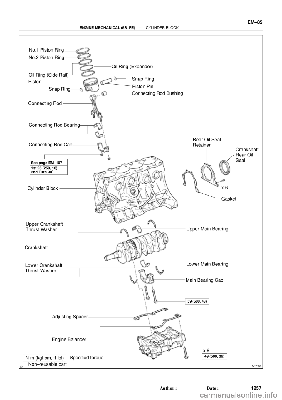
No.1 Piston Ring
No.2 Piston Ring
Oil Ring (Side Rail)
� Snap Ring
Connecting Rod
Connecting Rod Bearing
Connecting Rod Cap
Cylinder Block
Upper Crankshaft
Thrust Washer
Crankshaft
Lower Crankshaft
Thrust Washer
Adjusting Spacer
Engine Balancerx 6
Main Bearing CapLower Main Bearing Upper Main Bearing� Gasket Rear Oil Seal
Retainer
Crankshaft
Rear Oil
Seal � Connecting Rod BushingPiston Pin � Snap Ring Oil Ring (Expander)
� Non±reusable part
N´m (kgf´cm, ft´lbf)x 6 Piston
1st 25 (250, 18)
2nd Turn 90°
59 (600, 43)
49 (500, 36): Specified torque
See page EM±107
�
± ENGINE MECHANICAL (5S±FE)CYLINDER BLOCK
EM±85
1257 Author�: Date�:
Page 2660 of 4592
CYLINDER BLOCK
EM±109
1281 Author�: Date�:
(b) Align the bearing claw with the claw groove of the")
P03177
Mark
1, 2, 3, 4, or 5
P05354
P03173
S06012
P00104
1
10
735
84269
± ENGINE MECHANICAL (5S±FE)CYLINDER BLOCK
EM±109
1281 Author�: Date�:
(b) Align the bearing claw with the claw groove of the main
bearing cap, and push in the 5 lower bearings.
HINT:
A number is marked on each main bearing cap to indicate the
installation position.
5. INSTALL UPPER THRUST WASHERS
Install the 2 thrust washers under the No.3 journal position of
the cylinder block with the oil grooves facing outward.
6. PLACE CRANKSHAFT ON CYLINDER BLOCK
7. INSTALL MAIN BEARING CAPS AND LOWER
THRUST WASHERS
(a) Install the 2 thrust washers on the No.3 bearing cap with
the grooves facing outward.
(b) Install the 5 main bearing caps in their proper locations.
HINT:
Each bearing cap has a number and front mark.
(c) Apply a light coat of engine oil on the threads and under
the heads of the main bearing cap bolts.
(d) Install and uniformly tighten the 10 bolts of the main bear-
ing cap in several passes, in the sequence shown.
Torque: 59 N´m (600 kgf´cm, 43 ft´lbf)
(e) Check that the crankshaft turns smoothly.
8. CHECK CRANKSHAFT THRUST CLEARANCE
(See page EM±86)
Page 2661 of 4592

Front
N01001
Front Mark
(Protrusion)
Z19381
EM±110
± ENGINE MECHANICAL (5S±FE)CYLINDER BLOCK
1282 Author�: Date�:
9. INSTALL PISTON AND CONNECTING ROD AS-
SEM")
EM2082
A06614
Push Front Mark
(Cavity)
Front
N01001
Front Mark
(Protrusion)
Z19381
EM±110
± ENGINE MECHANICAL (5S±FE)CYLINDER BLOCK
1282 Author�: Date�:
9. INSTALL PISTON AND CONNECTING ROD AS-
SEMBLES
(a) Cover the connecting rod bolts with a short piece of hose
to protect the crankshaft from damage.
(b) Using a piston ring compressor, push the correctly num-
bered piston and connecting rod assemblies into each
cylinder with the front mark of the piston facing forward.
10. PLACE CONNECTING ROD CAP ON CONNECTING
ROD
(a) Match the numbered connecting rod cap with the con-
necting rod.
(b) Install the connecting rod cap with the front mark facing
forward.
11. INSTALL CONNECTING ROD CAP NUTS
HINT:
�The cap nuts are tightened in 2 progressive steps (steps
(b) and (d)).
�If any one of the connecting rod bolts is broken or de-
formed, replace it.
(a) Apply a light coat of engine oil on the threads and under
the nuts of the connecting rod cap.
(b) Install and alternately tighten the 2 cap nuts in several
passes.
Torque: 25 N´m (250 kgf´cm, 18 ft´lbf)
If any one of the cap nuts does not meet the torque specifica-
tion, replace the connecting rod bolt and cap nut as a set.
Page 2663 of 4592
CYLINDER BLOCK
1284 Author�: Date�:
(g) While pulling the center part of the engine balancer in the
direction of the arrow,")
S04614
1
Pull 53
426
P01477
Z19357
13
2 EM±112
± ENGINE MECHANICAL (5S±FE)CYLINDER BLOCK
1284 Author�: Date�:
(g) While pulling the center part of the engine balancer in the
direction of the arrow, uniformly tighten the 6 bolts in sev-
eral passes, in the sequence shown.
Torque: 49 N´m (500 kgf´cm, 36 ft´lbf)
(h) Recheck that the punch marks of the balance shafts are
aligned with the grooves of the No.2 housing.
14. CHECK AND ADJUST BACKLASH OF CRANKSHAFT
GEAR AND NO.1 BALANCE SHAFT GEAR
(See page EM±86)
15. INSTALL REAR OIL SEAL RETAINER
Install a new gasket and the retainer with the 6 bolts.
Torque: 13 N´m (130 kgf´cm, 9 ft´lbf)
16. INSTALL WATER PUMP, WATER BYPASS PIPE AND
OIL COOLER (w/ OIL COOLER) ASSEMBLY
(a) Install a new O±ring to the water pump cover.
(b) Install the water pump, water bypass pipe and oil cooler
(w/ oil cooler) assembly with the 3 bolts. Tighten the bolts
in the sequence shown.
Torque: 8.8 N´m (90 kgf´cm, 78 in.´lbf)
(c) Install the generator drive belt adjusting bar with the bolt.
Torque: 22 N´m (224 kgf´cm, 16 ft´lbf)
(d) w/ Oil Cooler:
Install the oil cooler. (See page LU±18)
17. INSTALL OIL FILTER (See page LU±2)
18. INSTALL KNOCK SENSOR 1 (See page SF±57)
19. INSTALL PS PUMP BRACKET
Install the PS pump bracket with the 3 bolts.
Torque: 43 N´m (440 kgf´cm, 32 ft´lbf)
20. INSTALL OIL PUMP AND OIL PAN
(a) Install the oil pump and oil pan. (See page LU±13)
(b) Install the crankshaft position sensor connector to the
generator drive belt adjusting bar.
21. INSTALL OIL DIPSTICK
22. INSTALL CYLINDER HEAD ASSEMBLY
(a) Install the cylinder head assembly. (See page EM±33)
(b) Install the 2 bolts holding the water bypass pipe to the cyl-
inder head.
Torque: 19 N´m (195 kgf´cm, 14 ft´lbf)
(c) Install the VSV for EGR to the cylinder head with the bolt.
(d) Connect the knock sensor 1 connector.
(e) Connect the crankshaft position sensor connector.
Page 2664 of 4592
± ENGINE MECHANICAL (5S±FE)CYLINDER BLOCK
EM±113
1285 Author�: Date�:
(f) Install the wire clamp to the generator drive belt adjusting
bar.
(g) Connect the IAC valve water bypass hose to the water by-
pass pipe.
(h) Connect the water bypass hose (from the water bypass
pipe) to the water outlet.
(i) Install the camshafts. (See page EM±53)
(j) Install the cylinder head cover.
(1) Install the cylinder head cover. (See page EM±53)
(2) Connect the PCV hose to the intake manifold.
(k) Install the No.3 timing belt cover with the 3 bolts.
Torque: 7.8 N´m (80 kgf´cm, 69 in.´lbf)
23. INSTALL TIMING BELT AND PULLEYS
(See page EM±23)
24. DISCONNECT ENGINE FROM ENGINE STAND
Page 2665 of 4592
EM08M±03
A07369
Heated Oxygen Sensor (Bank 1 Sensor 2)
HINT:
Before installing oxygen sensor, twist
sensor wire counterclockwise 3 and 1/2
turns.
After installing oxygen sensor, check that
sensor wire is not twisted. If it is twisted,
remove oxygen sensor and reinstall it.
Heat Insulator
Bracket
RingTailpipe
� Gasket
Center Exhaust Pipe
Heated Oxygen Sensor
(Bank 1 Sensor 2)
TWC (Except California)
Rear TWC (California)
Front Exhaust Pipe Bracket
StayBracket
N´m (kgf´cm, ft´lbf)
� Non±reusable part� Gasket
� Gasket
�Heat Insulator Heat Insulator
Heat Insulator
�
56 (570, 41)
44 (450, 32)
62 (630, 46)
56 (570, 41)
�Bracket
: Specified torqueRing �
�
19 (195, 14)
33 (330, 24)
33 (330, 24)
33 (330, 24)
EM±114
± ENGINE MECHANICAL (5S±FE)EXHAUST SYSTEM
1286 Author�: Date�:
EXHAUST SYSTEM
COMPONENTS
Page 2678 of 4592
EM04N±03
A06654
RH Fender Apron Seal
Generator Drive Belt Engine Moving
Control Rod
RH Engine Mounting Stay
No.2 RH Engine
Mounting Bracket
Ground Strap PS Pump Drive Belt
Engine Coolant Reservoir Hose
: Specified torqueNo.2 RH Engine
Mounting Stay (M/T)
64 (650, 47)
32 (320, 23)
64 (650, 47)
N´m (kgf´cm, ft´lbf)
± ENGINE MECHANICAL (1MZ±FE)TIMING BELT
EM±13
1299 Author�: Date�:
TIMING BELT
COMPONENTS
Page 2679 of 4592
B06384
No.2 Timing Belt CoverTiming Belt
Gasket
Timing Belt Guide
No.2 Generator
Bracket RH Engine Mounting Bracket
Crankshaft
PulleyGasket
Engine Wire
Protector
RH Camshaft Timing Pulley
No.2 Idler Pulley
Crankshaft
Timing PulleyDust Boot
Timing Belt Plate Plate Washer
�
Timing Belt Tensioner
N´m (kgf´cm, ft´lbf)
: Specified torque
� Non±reusable part No.1 Timing Belt Cover
LH Camshaft
Timing Pulley
No.1 Idler Pulley
� Precoated part
* For use with SST
28 (290, 21)
215 (2,200, 159)
125 (1,300, 94)*88 (900, 65)43 (440, 32)
34 (350, 25)
27 (280, 20)
125 (1,300, 94)
EM±14
± ENGINE MECHANICAL (1MZ±FE)TIMING BELT
1300 Author�: Date�:


HINT:
Before installing oxygen sensor, twist
sensor wire counterclockwise 3 and 1/2
turns.
After installing oxygen sensor, check that
sensor wir")

