Page 2743 of 4592
ENGINE UNIT
1364 Author�: Date�:
14. INSTALL PS PUMP
(a) Install the PS pump with the 2 bolts.
Torque: 43 N´m (440")
P18775
B00881
ConnectorBracket
A
B
A
A
C
S04497
EM±78
± ENGINE MECHANICAL (1MZ±FE)ENGINE UNIT
1364 Author�: Date�:
14. INSTALL PS PUMP
(a) Install the PS pump with the 2 bolts.
Torque: 43 N´m (440 kgf´cm, 31 ft´lbf)
(b) Install the drive belt.
(c) Connect the PS pressure tube with the 2 nuts.
15. INSTALL A/C COMPRESSOR
(a) Install the A/C compressor and drive belt adjusting bar
bracket with the 4 bolts and nut.
Torque:
Bolt A: 25 N´m (250 kgf´cm, 18 ft´lbf)
Bolt B: 18 N´m (185 kgf´cm, 13 ft´lbf)
Nut C: 25 N´m (250 kgf´cm, 18 ft´lbf)
(b) Install the drive belt.
(c) Connect the A/C compressor connector.
16. M/T only:
INSTALL CLUTCH RELEASE CYLINDER AND
ACCUMULATOR
17. M/T only:
INSTALL STARTER (See page ST±19)
18. INSTALL DRIVE SHAFTS (See page SA±32)
19. CONNECT ENGINE WIRE TO CABIN
(a) Push in the engine wire through the cowl panel. Install the
grommet.
(b) Connect the 3 engine ECM connectors.
(c) Connect the 3 cowl wire connectors to the connectors on
the bracket.
(d) Install the No.2 instrument lower panel.
20. CONNECT CONNECTORS, CABLE, CLAMPS AND
HOSES
(a) Connect the igniter connector on the LH fender apron.
(b) Connect the noise filter connector on the LH fender
apron.
(c) Connect the generator connector and wire.
(d) Connect the starter connector and wire.
(e) Connect the 2 ground strap connectors to the RH fender
apron.
Page 2744 of 4592
ENGINE UNIT
EM±79
1365 Author�: Date�:
(f) Connect the 2 ground strap connectors to the LH fender
apron.
(g) Connect the DLC1 to the RH fender apron.
(h) Connect")
S05048
± ENGINE MECHANICAL (1MZ±FE)ENGINE UNIT
EM±79
1365 Author�: Date�:
(f) Connect the 2 ground strap connectors to the LH fender
apron.
(g) Connect the DLC1 to the RH fender apron.
(h) Connect the ground cable to the battery body bracket.
(i) Connect the engine wire protector clamp to the battery
body bracket.
(j) Connect the engine wire clamp to the bracket on the RH
fender apron.
(k) Connect the engine wire clamp to the bracket on the fuel
filter.
(l) Connect the brake booster vacuum hose to the air intake
chamber.
(m) Connect the engine coolant reservoir hose to the water
outlet.
(n) Connect the heater hose to the intake manifold.
(o) Connect the heater hose to the water inlet housing.
(p) Connect the fuel inlet hose to the fuel filter.
CAUTION:
Perform connecting operations of the fuel tube connector
(quick type) after observing the precautions.
(See page SF±6)
(q) Connect the purge hose to the pipe on the emission con-
trol valve set.
(r) Connect the 2 vacuum hoses to the vacuum tank for the
ACIS.
21. INSTALL FRONT EXHAUST PIPE
(a) Temporarily install 3 new gaskets and the front exhaust
pipe with the 2 bolts and 6 nuts.
(b) Tighten the 4 nuts holding the exhaust manifolds to the
front exhaust pipe.
Torque: 62 N´m (630 kgf´cm, 46 ft´lbf)
(c) Tighten the 2 bolts and 2 nuts holding the front exhaust
pipe to the center exhaust pipe.
Torque: 56 N´m (570 kgf´cm, 41 ft´lbf)
(d) Install the bracket with the 2 bolts.
Torque: 33 N´m (330 kgf´cm, 24 ft´lbf)
(e) Install the support stay with the 2 bolts.
Torque: 33 N´m (330 kgf´cm, 24 ft´lbf)
22. INSTALL RADIATOR (See page CO±24)
23. INSTALL CRUISE CONTROL ACTUATOR
24. INSTALL AIR CLEANER CAP ASSEMBLY AND AIR
CLEANER CASE
25. CONNECT ACCELERATOR CABLE
26. INSTALL ENGINE FENDER APRON SEALS
27. INSTALL BATTERY TRAY AND BATTERY
Page 2746 of 4592

No.2 Idler Pulley Bracket
Water Seal Plate
Engine Cool")
EM050±03
A06640
Knock Sensor Connector
Engine Wire Band
Engine WireKnock Sensor
No.2 ECT Switch Connector
Water Inlet Housing
(With Water Inlet)
No.2 Idler Pulley Bracket
Water Seal Plate
Engine Coolant
Drain Union
Oil Filter Union
Oil Filter � Gasket
EGR Cooler
� Gasket
Water Pump
� Crankshaft
Front Oil Seal
Crankshaft
Position Sensor
Connector� Oil Pressure Switch
Oil Pressure Switch
ConnectorA/C Compressor
Housing Bracket
No.1 Oil Pan
x 15 or 17 Oil Pump
� Gasket
� Gasket
Engine Wire
Generator
Drain Plugx 10No.2 Oil Pan Oil Strainer
� Non±reusable part
N´m (kgf´cm, ft´lbf) : Specified torque
Precoated part �
x 8
�
� O±Ring
x 9
9 (90, 78 in.´lbf)
8 (80, 69 in.´lbf)
10mm Head 7.8 (80, 69 in.´lbf)
12mm Head 19.5 (200,14)
39 (400, 29)
28 (290, 21)
14.5 (145, 10)
25 (250, 18)
10mm Head 8 (80, 69 in.´lbf)
12mm Head 19.5 (200,14)
8 (80, 69 in.´lbf)
8 (80, 69 in.´lbf)45 (460, 33)
8 (80, 69 in.´lbf)
or 0 or 0
± ENGINE MECHANICAL (1MZ±FE)CYLINDER BLOCK
EM±81
1367 Author�: Date�:
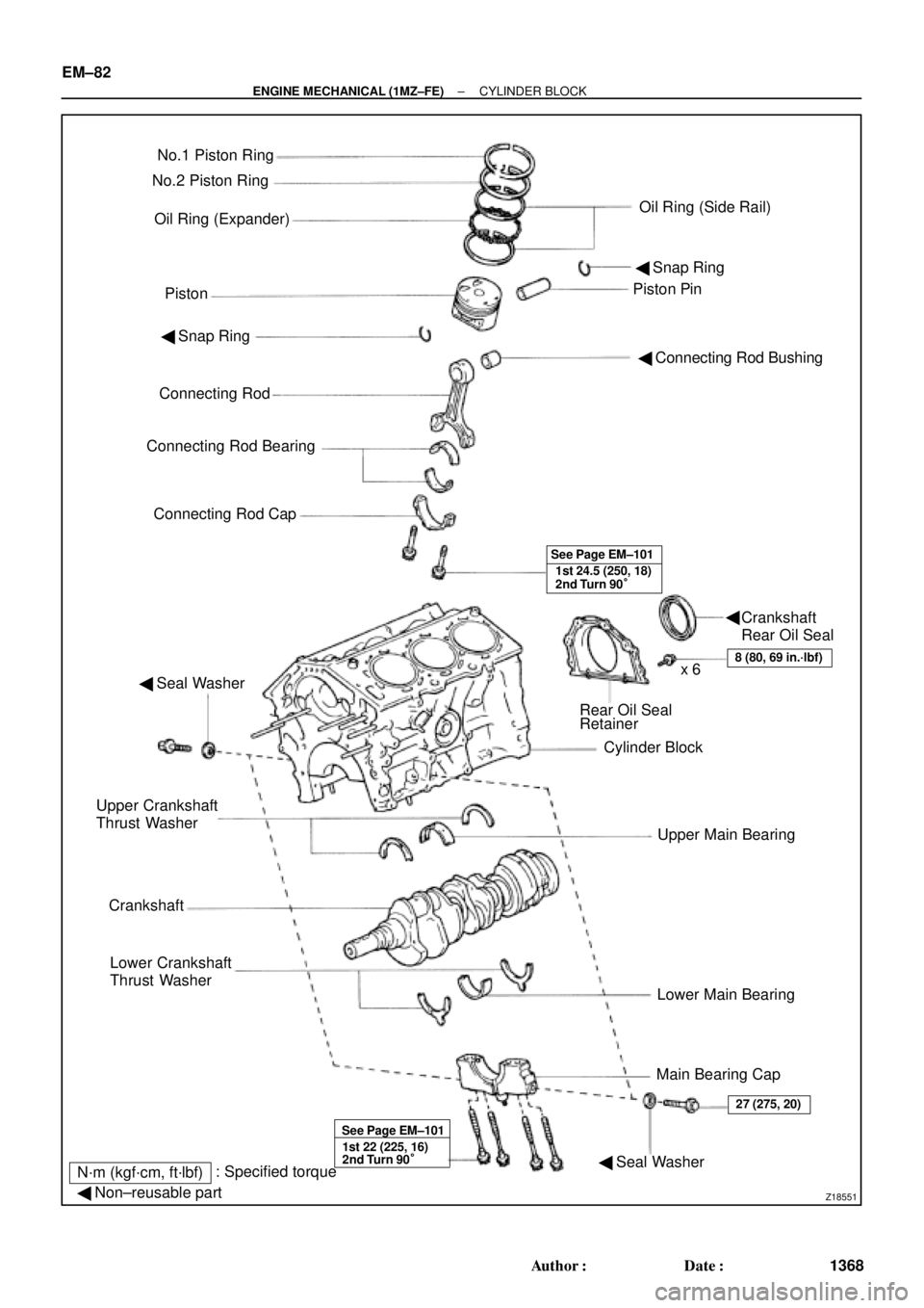
CYLINDER BLOCK
COMPONENTS
Page 2747 of 4592
Z18551
No.1 Piston Ring
Oil Ring (Expander)
PistonPiston Pin No.2 Piston Ring
Oil Ring (Side Rail)
� Snap Ring
� Connecting Rod Bushing � Snap Ring
Connecting Rod
Connecting Rod Bearing
Connecting Rod Cap
1st 24.5 (250, 18)
2nd Turn 90° See Page EM±101
� Seal Washer
Rear Oil Seal
Retainer
Cylinder Block
Upper Main Bearing
Lower Main Bearing
Main Bearing Cap Upper Crankshaft
Thrust Washer
Crankshaft
Lower Crankshaft
Thrust Washer
8 (80, 69 in.´lbf)x 6
1st 22 (225, 16)
2nd Turn 90° See Page EM±101
� Seal Washer
27 (275, 20)
N´m (kgf´cm, ft´lbf): Specified torque
� Non±reusable part
Crankshaft
Rear Oil Seal � EM±82
± ENGINE MECHANICAL (1MZ±FE)CYLINDER BLOCK
1368 Author�: Date�:
Page 2751 of 4592
CYLINDER BLOCK
1372 Author�: Date�:
(g) Install the connecting rod cap with the 2 bolts.
(See page EM±101)
Tor")
P12697
P12698
P14127
Number Mark
Number
Mark
P12500
EM±86
± ENGINE MECHANICAL (1MZ±FE)CYLINDER BLOCK
1372 Author�: Date�:
(g) Install the connecting rod cap with the 2 bolts.
(See page EM±101)
Torque:
1st: 24.5 N´m (250 kgf´cm, 18 ft´lbf)
2nd: Turn extra 90°
NOTICE:
Do not turn the crankshaft.
(h) Remove the 2 bolts, connecting rod cap and lower bear-
ing. (See steps (b) and (c))
(i) Measure the Plastigage at its widest point.
Standard oil clearance:
0.038 ± 0.064 mm (0.0015 ± 0.0025 in.)
Maximum oil clearance: 0.08 mm (0.0031 in.)
If the oil clearance is greater than maximum, replace the bear-
ings. If necessary, grind or replace the crankshaft.
HINT:
If replacing a bearing, replace it with one having the same num-
ber as marked on the connecting rod. There are 4 sizes of stan-
dard bearings, marked º1º, º2º, º3º and º4º accordingly.
Reference:
Standard bearing center wall thickness:
Markmm (in.)
º1º1.484 ± 1.487 (0.0584 ± 0.0585)
º2º1.487 ± 1.490 (0.0585 ± 0.0587)
º3º1.490 ± 1.493 (0.0587 ± 0.0588)
º4º1.493 ± 1.496 (0.0588 ± 0.0589)
(j) Completely remove the Plastigage.
25. REMOVE PISTON AND CONNECTING ROD
ASSEMBLIES
(a) Using a ridge reamer, remove all the carbon from the top
of the cylinder.
(b) Push the piston, connecting rod assembly and upper
bearing through the top of the cylinder block.
HINT:
�Keep the bearings, connecting rod and cap together.
�Arrange the piston and connecting rod assemblies in the
correct order.
Page 2753 of 4592
CYLINDER BLOCK
1374 Author�: Date�:
(d) Lift out the crankshaft.
HINT:
Keep the upper bearings together with the cylinder bl")
P12495
P12980
Plastigage
P12954
P12993
EM±88
± ENGINE MECHANICAL (1MZ±FE)CYLINDER BLOCK
1374 Author�: Date�:
(d) Lift out the crankshaft.
HINT:
Keep the upper bearings together with the cylinder block.
(e) Clean each main journal and bearing.
(f) Check each main journal and bearing for pitting and
scratches.
If the journal or bearing is damaged, replace the bearings. If
necessary, replace the crankshaft.
(g) Place the crankshaft on the cylinder block.
(h) Lay a strip of Plastigage across each journal.
(i) Install the 4 main bearing caps. (See page EM±101)
Torque:
12 pointed head bolts:
1st: 22 N´m (225 kgf´cm, 16 ft´lbf)
2nd: Turn extra 90°
Hexagon head bolts:
27 N´m (275 kgf´cm, 20 ft´lbf)
NOTICE:
Do not turn the crankshaft.
(j) Remove the main bearing caps. (See steps (a) to (c) )
(k) Measure the Plastigage at its widest point.
Standard oil clearance:
No.1 and No.4 journals0.014 ± 0.036 mm (0.0006 ± 0.0014 in.)
No.2 and No.3 journals0.026 ± 0.048 mm (0.0010 ± 0.0019 in.)
Maximum clearance:
No.1 and No.4 journals0.05 mm (0.0020 in.)
No.2 and No.3 journals0.06 mm (0.0024 in.)
If the oil clearance is greater than maximum, replace the bear-
ings. If necessary, replace the crankshaft.
Page 2770 of 4592
CYLINDER BLOCK
EM±105
1391 Author�: Date�:
(a) Apply a light coat of eng")
P12753
10 11
12 13
14
151
162
3
45
6
7
89
P25741
Painted Mark
Front90°
90°
P12586
1
2
34
567
8
± ENGINE MECHANICAL (1MZ±FE)CYLINDER BLOCK
EM±105
1391 Author�: Date�:
(a) Apply a light coat of engine oil on the threads and under
the main bearing cap bolts.
(b) Install and uniformly tighten the 16 main bearing cap
bolts, in several passes, in the sequence shown.
Torque: 22 N´m (225 kgf´cm, 16 ft´lbf)
If any of the main bearing cap bolts does not meet the torque
specification, replace the main bearing cap bolt.
(c) Mark the front of the main bearing cap bolts with paint.
(d) Retighten the main bearing cap bolts by 90° in the numer-
ical order shown.
(e) Check that the painted mark is now at a 90° angle to the
front.
9. INSTALL HEXAGON HEAD MAIN BEARING CAP
BOLTS
(a) Install a new seal washer to the main bearing cap bolt.
(b) Install and uniformly tighten the 8 main bearing cap bolts,
in several passes, in the sequence shown.
Torque: 27 N´m (275 kgf´cm, 20 ft´lbf)
(c) Check that the crankshaft turns smoothly.
10. CHECK CRANKSHAFT THRUST CLEARANCE
(See page EM±83)
Page 2772 of 4592
CYLINDER BLOCK
EM±107
1393 Author�: Date�:
(a) Apply a light coat of engine oil on the threa")
P12697
P25743
Painted Mark
Front90°
90°
P12911
Seal Width
2 ± 3 mm A
BA
B
± ENGINE MECHANICAL (1MZ±FE)CYLINDER BLOCK
EM±107
1393 Author�: Date�:
(a) Apply a light coat of engine oil on the threads and under
the heads of the connecting rod cap bolts.
(b) Install and alternately tighten the 2 connecting rod cap
bolts in several passes.
Torque: 24.5 N´m (250 kgf´cm, 18 ft´lbf)
If any of the connecting rod cap bolts does not meet the torque
specification, replace the connecting rod cap bolts.
(c) Mark the front of the connecting cap bolts with paint.
(d) Retighten the cap bolts by 90° as shown.
(e) Check that the painted mark is now at a 90° angle to the
front.
(f) Check that the crankshaft turns smoothly.
14. CHECK CONNECTING ROD THRUST
CLEARANCE (See page EM±83)
15. INSTALL REAR OIL SEAL RETAINER
(a) Remove any old packing (FIPG) material and be careful
not to drop any oil on the contact surfaces of the oil seal
retainer and cylinder block.
�Using a razor blade and gasket scraper, remove all
the oil packing (FIPG) material from the gasket sur-
faces and sealing grooves.
�Thoroughly clean all components to remove all the
loose material.
�Using a non±residue solvent, clean both sealing
surfaces.
(b) Apply seal packing to the oil seal retainer as shown in the
illustration.
Seal packing: Part No. 08826±00080 or equivalent
�Install a nozzle that has been cut to a 2 ± 3 mm (0.08
± 0.12 in.) opening.
�Parts must be assembled within 3 minutes of ap-
plication. Otherwise the material must be removed
and reapplied.
�Immediately remove nozzle from the tube and rein-
stall cap.
(c) Install the oil seal retainer with the 6 bolts Uniformly tight-
en the bolt in several passes, in the sequence shown.
Torque: 8 N´m (80 kgf´cm, 69 in.´lbf)
16. INSTALL EGR COOLER
Install a new gasket and the EGR cooler with the 3 bolts and 2
nuts.
Torque: 9 N´m (90 kgf´cm, 78 in.´lbf)