Page 2886 of 4592

IACIdle Air ControlIdle Speed Control (ISC)
IATIntake Air TemperatureIntake or Inlet Air Temperature
ICMIgnition Contro")
IN±40
± INTRODUCTIONTERMS
HO2S
Heated Oxygen SensorHeated Oxygen Sensor (HO2S)
IACIdle Air ControlIdle Speed Control (ISC)
IATIntake Air TemperatureIntake or Inlet Air Temperature
ICMIgnition Control Module±
IFIIndirect Fuel InjectionIndirect Injection (IDL)
IFSInertia Fuel±Shutoff±
ISCIdle Speed Control±
KSKnock SensorKnock Sensor
MAFMass Air FlowAir Flow Meter
MAPManifold Absolute PressureManifold Pressure
Intake Vacuum
MCMixture Control
Electric Bleed Air Control Valve (EBCV)
Mixture Control Valve (MCV)
Electric Air Control Valve (EACV)
MDPManifold Differential Pressure±
MFIMultiport Fuel InjectionElectronic Fuel Injection (EFI)
MILMalfunction Indicator LampCheck Engine Lamp
MSTManifold Surface Temperature±
MVZManifold Vacuum Zone±
NVRAMNon±Volatile Random Access Memory±
O2SOxygen SensorOxygen Sensor, O2 Sensor (O2S)
OBDOn±Board DiagnosticOn±Board Diagnostic System (OBD)
OCOxidation Catalytic ConverterOxidation Catalyst Convert (OC), CCo
OPOpen LoopOpen Loop
PAIRPulsed Secondary Air InjectionAir Suction (AS)
PCMPowertrain Control Module±
PNPPark/Neutral Position±
PROMProgrammable Read Only Memory±
PSPPower Steering Pressure±
PTOXPeriodic Trap OxidizerDiesel Particulate Filter (DPF)
Diesel Particulate Trap (DPT)
RAMRandom Access MemoryRandom Access Memory (RAM)
RMRelay Module±
ROMRead Only MemoryRead Only Memory (ROM)
RPMEngine SpeedEngine Speed
SCSuperchargerSupercharger
SCBSupercharger BypassE±ABV
SFISequential Multiport Fuel InjectionElectronic Fuel Injection (EFI), Sequential Injection
SPLSmoke Puff Limiter±
SRIService Reminder Indicator±
SRTSystem Readiness Test±
STScan Tool±
TBThrottle BodyThrottle Body
TBIThrottle Body Fuel InjectionSingle Point Injection
Central Fuel Injection (Ci)
TCTurbochargerTurbocharger
TCCTorque Converter ClutchTorque Converter
Page 2890 of 4592
S05320
SST
3/4
Turn
± LUBRICATION (5S±FE)OIL AND FILTER
LU±3
1649 Author�: Date�:
(e) Using SST, give it an additional 3/4 turn to seat the filter.
SST 09228±06501
3. FILL WITH ENGINE OIL
(a) Clean and install the oil drain plug with a new gasket.
Torque: 37 N´m (375 kgf´cm, 27 ft´lbf)
(b) Fill with new engine oil.
Capacity:
Drain and refill w/ Oil filter change
w/o Oil filter change3.6 liters (3.8 US qts, 3.2 lmp. qts)
3.4 liters (3.6 US qts, 3.0 lmp. qts)
Dry fill w/ Oil cooler
w/o Oil cooler4.3 liters (4.5 US qts, 3.8 lmp. qts)
4.2 liters (4.4 US qts, 3.7 lmp. qts)
(c) Reinstall the oil filler cap.
4. START ENGINE AND CHECK FOR OIL LEAKS
5. RECHECK ENGINE OIL LEVEL
Page 2891 of 4592
LU03J±03
S05595
Engine Moving Control Rod
No.2 RH Engine Mounting Bracket
Generator Drive Belt
RH Front Fender Apron Seal
PS Pump Drive Belt
Exhaust Pipe Bracket
Oil Pan InsulatorGround Strap Connector
No.2 Rear End Plate
No.2 Exhaust
Manifold Stay
(TMMK Made)
(TMC Made)LH Stiffener Plate
� Gasket
Bracket
Front Exhaust Pipe
StayBracket� Gasket
N´m (kgf´cm, ft´lbf): Specified torque
� Non±reusable part
64 (650, 47)
52 (530, 38)
62 (630, 46)56 (570, 41) 64 (650, 47)
��
� LU±4
± LUBRICATION (5S±FE)OIL PUMP
1650 Author�: Date�:
OIL PUMP
COMPONENTS
Page 2892 of 4592
B06345
No.2 Timing Belt Cover
No.1 Timing Belt Cover* Gasket
Wire
ClampGeneratorGenerator Wire
Generator Connector
Crankshaft Pulley
No.2 Idler Pulley
Oil Pump Pulley
Crankshaft
Timing Pulley
Crankshaft Position SensorTiming Belt Guide
Wire ClampWire
Clamp
Timing Belt
Clamp
No.1 Idler Pulley
Tension Spring � GasketClamp
� Gasket
� GasketHigh±Tension Cord
Spark Plug
Oil Strainer
Drain Plug
N´m (kgf´cm, ft´lbf): Specified torque
� Non±reusable partx 17
* Gasket
* Replace only if damagedOil Pump
x 10
8.8 (90, 78 in.´lbf)5.4 (55, 48 in.´lbf)
5.4 (55, 48 in.´lbf)
24 (245, 18)
42 (425, 31)
108 (1,100, 80)
18 (180, 13)
42 (425, 31)
Oil Pan
± LUBRICATION (5S±FE)OIL PUMP
LU±5
1651 Author�: Date�:
Page 2893 of 4592
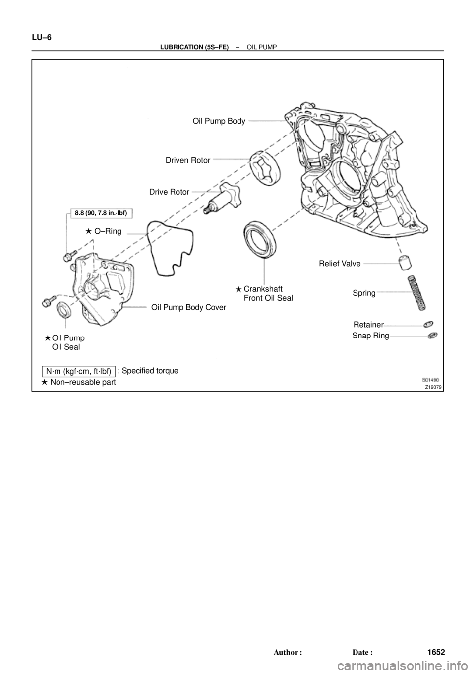
Z19079
Oil Pump Body
Driven Rotor
Drive Rotor
Oil Pump Body Cover
Oil Pump
Oil SealCrankshaft
Front Oil SealRelief Valve
Spring
Retainer
Snap Ring
N´m (kgf´cm, ft´lbf): Specified torque
� Non±reusable part ��
8.8 (90, 7.8 in.´lbf)
� O±Ring LU±6
± LUBRICATION (5S±FE)OIL PUMP
1652 Author�: Date�:
Page 2899 of 4592
LU0FP±01
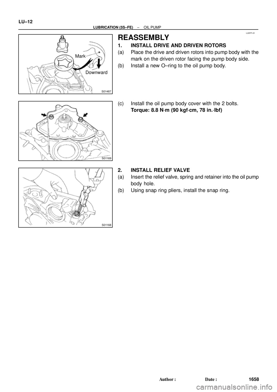
S01487
Downward Mark
S01169
S01168
LU±12
± LUBRICATION (5S±FE)OIL PUMP
1658 Author�: Date�:
REASSEMBLY
1. INSTALL DRIVE AND DRIVEN ROTORS
(a) Place the drive and driven rotors into pump body with the
mark on the driven rotor facing the pump body side.
(b) Install a new O±ring to the oil pump body.
(c) Install the oil pump body cover with the 2 bolts.
Torque: 8.8 N´m (90 kgf´cm, 78 in.´lbf)
2. INSTALL RELIEF VALVE
(a) Insert the relief valve, spring and retainer into the oil pump
body hole.
(b) Using snap ring pliers, install the snap ring.
Page 2900 of 4592

± LUBRICATION (5S±FE)OIL PUMP
LU±13
1659 Author�: Date�:
INSTALLATION
1. INSTALL OIL PUMP
Install")
LU03P±03
Z19249
A
BB AA A AA A
A A
A
S05928
LU0420
Seal Width
3 ± 5 mm
A
A
BBC
C
5 mm (0.20 in.)
± LUBRICATION (5S±FE)OIL PUMP
LU±13
1659 Author�: Date�:
INSTALLATION
1. INSTALL OIL PUMP
Install a new gasket and the oil pump with the 12 bolts. Uniformi-
ty tighten the bolts in several passes.
Torque: 8.8 N´m (90 kgf´cm, 78 in.´lbf)
HINT:
Each bolt length is indicated in the illustration.
Bolt length:
25 mm (0.98 in.) for A
35 mm (1.38 in.) for B
2. INSTALL OIL PUMP PULLEY (See page EM±23)
3. INSTALL CRANKSHAFT TIMING PULLEY
(See page EM±23)
4. INSTALL NO.2 IDLER PULLEY (See page EM±23)
5. INSTALL TIMING BELT (See page EM±23)
6. INSTALL OIL STRAINER
Install a new gasket and the oil strainer with the bolt and 2 nuts.
Torque: 5.4 N´m (55 kgf´cm, 48 in.´lbf)
7. INSTALL OIL PAN
(a) Remove any old seal packing (FIPG) material and be
careful not to drop any oil on the contact surfaces of the
oil pan and cylinder block.
�Using a razor blade and gasket scraper, remove all
the old packing (FIPG) material from the gasket sur-
faces and sealing groove.
�Thoroughly clean all components to remove all the
loose material.
�Using a non±residue solvent, clean both sealing
surface.
NOTICE:
Do not use a solvent which will affect the painted surfaces.
(b) Apply seal packing to the oil pan shown in the illustration.
Seal packing: Part No. 08826±00080 or equivalent
�Install a nozzle that has been cut to a 3 ± 5 mm (0.12
± 0.20 in.) opening.
�Parts must be assembled within 5 minutes of ap-
plication. Otherwise the material must be removed
and reapplied.
Page 2902 of 4592
LU03Q±03
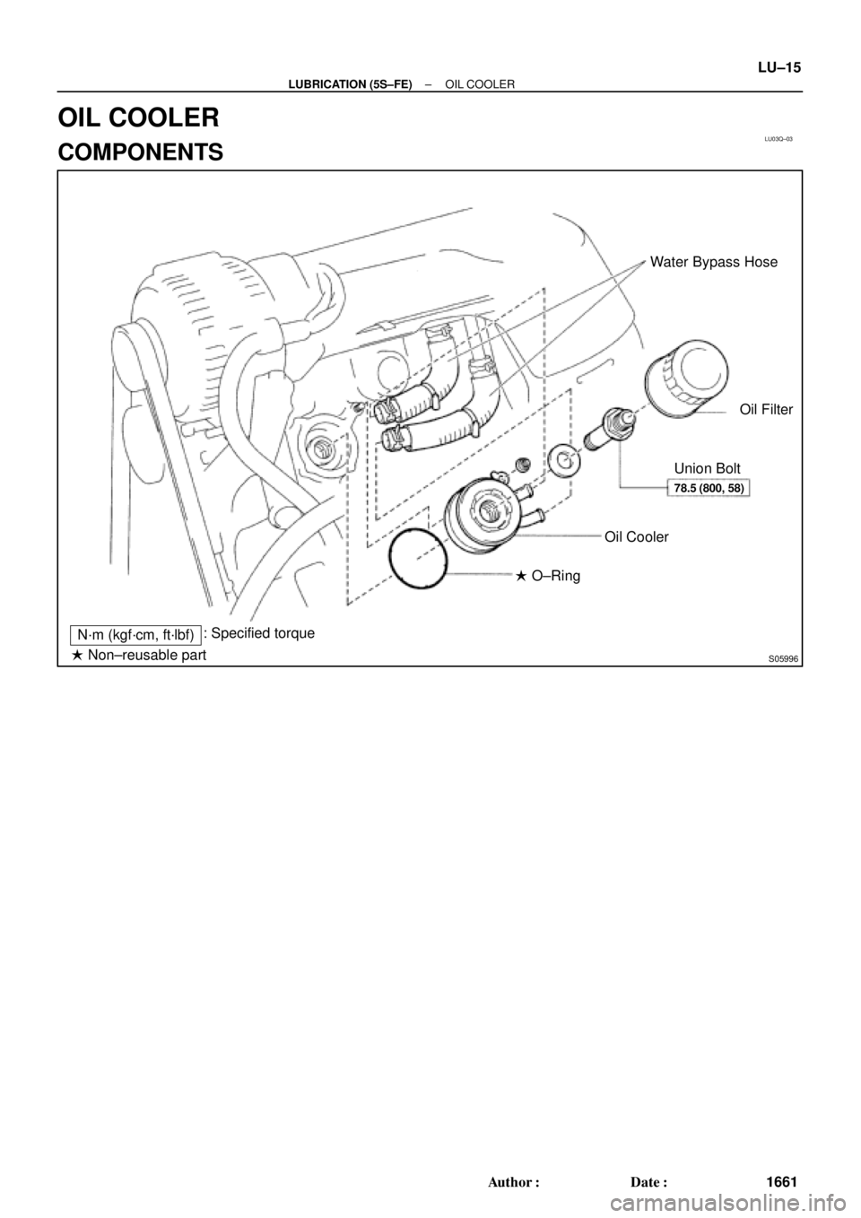
S05996
Water Bypass Hose
Oil Filter
Union Bolt
Oil Cooler
� O±Ring
N´m (kgf´cm, ft´lbf): Specified torque
� Non±reusable part
78.5 (800, 58)
± LUBRICATION (5S±FE)OIL COOLER
LU±15
1661 Author�: Date�:
OIL COOLER
COMPONENTS