Page 2905 of 4592
LU03T±03
S05930
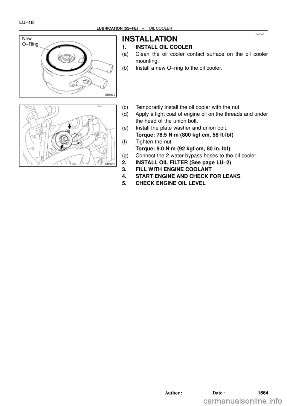
New
O±Ring
S05613
LU±18
± LUBRICATION (5S±FE)OIL COOLER
1664 Author�: Date�:
INSTALLATION
1. INSTALL OIL COOLER
(a) Clean the oil cooler contact surface on the oil cooler
mounting.
(b) Install a new O±ring to the oil cooler.
(c) Temporarily install the oil cooler with the nut.
(d) Apply a light coat of engine oil on the threads and under
the head of the union bolt.
(e) Install the plate washer and union bolt.
Torque: 78.5 N´m (800 kgf´cm, 58 ft´lbf)
(f) Tighten the nut.
Torque: 9.0 N´m (92 kgf´cm, 80 in.´lbf)
(g) Connect the 2 water bypass hoses to the oil cooler.
2. INSTALL OIL FILTER (See page LU±2)
3. FILL WITH ENGINE COOLANT
4. START ENGINE AND CHECK FOR LEAKS
5. CHECK ENGINE OIL LEVEL
Page 2907 of 4592
P12478
Adhesive
LU±2
± LUBRICATION (1MZ±FE)OIL AND FILTER
1666 Author�: Date�:
6. REMOVE OIL PRESSURE GAUGE AND REINSTALL
OIL PRESSURE SWITCH
(a) Remove the oil pressure gauge.
(b) Apply adhesive to 2 or 3 threads of the oil pressure switch.
Adhesive: Part No. 08833±00080, THREE BOND 1344,
LOCTITE 242 or equivalent
(c) Using SST, install the oil pressure switch.
SST 09816±30010
Torque: 13 N´m (130 kgf´cm, 9 ft´lbf)
7. START ENGINE AND CHECK FOR LEAKS
Page 2909 of 4592
LU±4
± LUBRICATION (1MZ±FE)OIL AND FILTER
1668 Author�: Date�:
3. REFILL WITH ENGINE OIL
(a) Clean and install the oil drain plug with a new gasket.
Torque: 45 N´m (460 kgf´cm, 33 ft´lbf)
(b) Fill with fresh engine oil.
Capacity:
Drain and refill w/ Oilfilter change
w/o Oilfilter change4.7 liters (5.0 US qts, 4.1 lmp. qts)
4.5 liters (4.8 US qts, 4.0 lmp. qts)
Dry fill5.2 liters (5.5 US qts, 4.6 lmp. qts)
(c) Install the oil filler cap.
4. START ENGINE AND CHECK FOR OIL LEAKS
5. RECHECK ENGINE OIL LEVEL
Page 2910 of 4592
LU027±04
B06398
� Gasket RH Fender Apron Seal
PS Pump Drive Belt
A/C Compressor
Connector
A/C Compressor
No.2 RH Engine
Mounting Stay (M/T) Engine Moving
Control Rod
RH Engine Mounting Stay
No.2 RH Engine Mounting
Bracket
Ground Strap
Bracket
Front Exhaust Pipe
Stay
�
PS Pump Drive Belt
Adjusting Strut
Generator Drive Belt
Adjusting Bar Bracket
� Gasket
�
64 (650, 47)
62 (630, 46)
33 (330, 24)
21 (210, 15)
56 (570, 41)
64 (650, 47)
32 (320, 23)
62 (630, 46)
33 (330, 24)
N´m (kgf´cm, ft´lbf) : Specified torque
� Non±reusable part
Bracket
Generator Drive
Belt
Radiator Reservoir Hose
± LUBRICATION (1MZ±FE)OIL PUMP
LU±5
1669 Author�: Date�:
OIL PUMP
COMPONENTS
Page 2911 of 4592
B06384
No.2 Timing Belt CoverTiming Belt
Gasket
Timing Belt Guide
No.2 Generator
Bracket RH Engine Mounting Bracket
Crankshaft
PulleyGasket
Engine Wire
Protector
RH Camshaft Timing Pulley
No.2 Idler Pulley
Crankshaft
Timing PulleyDust Boot
Timing Belt Plate Plate Washer
�
Timing Belt Tensioner
N´m (kgf´cm, ft´lbf) : Specified torque
� Non±reusable part No.1 Timing Belt Cover
LH Camshaft
Timing Pulley
No.1 Idler Pulley
� Precoated part
* For use with SST
28 (290, 21)
215 (2,200, 159)
125 (1,300, 94)*88 (900, 65)43 (440, 32)
34 (350, 25)
27 (280, 20)
125 (1,300, 94)
LU±6
± LUBRICATION (1MZ±FE)OIL PUMP
1670 Author�: Date�:
Page 2912 of 4592
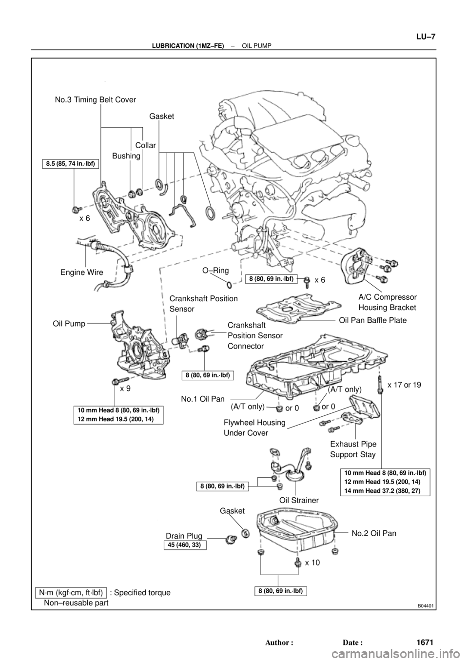
B04401
N´m (kgf´cm, ft´lbf) : Specified torque
� Non±reusable partNo.3 Timing Belt Cover
Gasket
BushingCollar
A/C Compressor
Housing Bracket
Oil Pan Baffle Plate
Crankshaft
Position Sensor
Connector Crankshaft Position
Sensor
Oil PumpEngine Wire
Flywheel Housing
Under Cover
Exhaust Pipe
Support Stay
Oil Strainer
No.2 Oil Pan
x 10x 6
x 9� O±Ring
No.1 Oil Pan
� Gasket
Drain Plug
8.5 (85, 74 in.´lbf)
8 (80, 69 in.´lbf)
8 (80, 69 in.´lbf)
10 mm Head 8 (80, 69 in.´lbf)
12 mm Head 19.5 (200, 14)
10 mm Head 8 (80, 69 in.´lbf)
12 mm Head 19.5 (200, 14)
14 mm Head 37.2 (380, 27)
8 (80, 69 in.´lbf)
45 (460, 33)
8 (80, 69 in.´lbf)
x 6
x 17 or 19
(A/T only)(A/T only)or 0or 0
± LUBRICATION (1MZ±FE)OIL PUMP
LU±7
1671 Author�: Date�:
Page 2913 of 4592
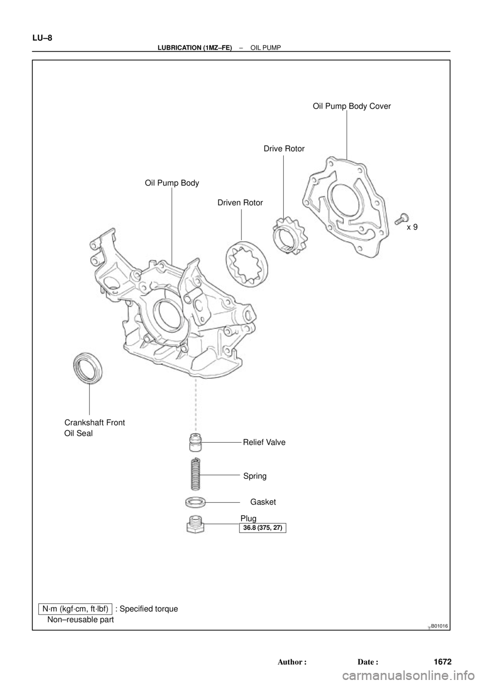
B01016
N´m (kgf´cm, ft´lbf) : Specified torque
� Non±reusable partx 9
� Gasket � Crankshaft Front
Oil Seal
Relief Valve
Spring
Plug Oil Pump Body
Driven RotorDrive RotorOil Pump Body Cover
36.8 (375, 27)
LU±8
± LUBRICATION (1MZ±FE)OIL PUMP
1672 Author�: Date�:
Page 2919 of 4592
LU02C±03
P12807
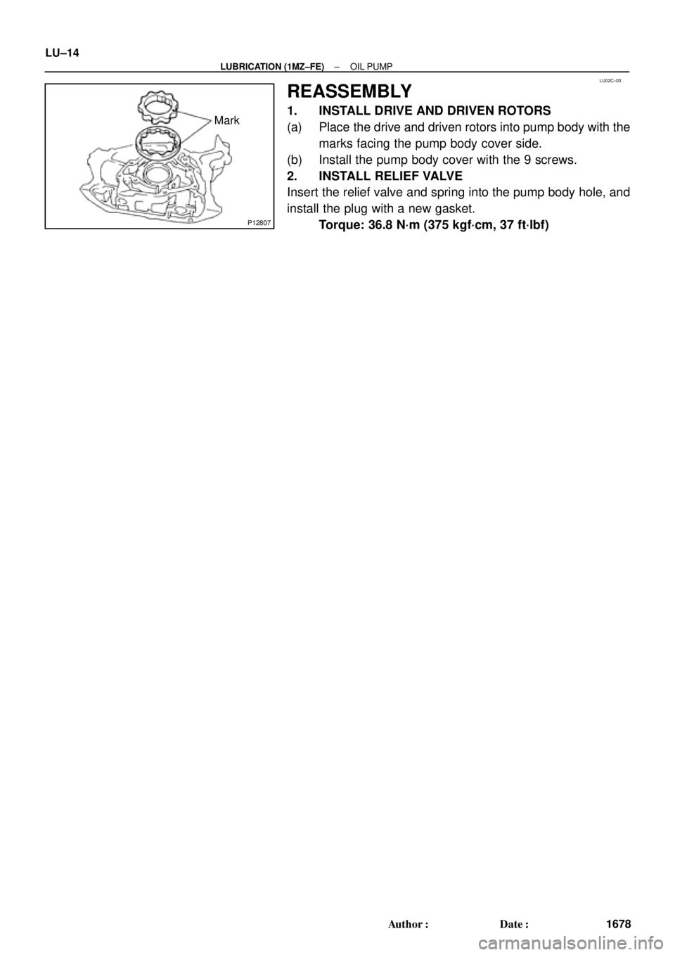
Mark LU±14
± LUBRICATION (1MZ±FE)OIL PUMP
1678 Author�: Date�:
REASSEMBLY
1. INSTALL DRIVE AND DRIVEN ROTORS
(a) Place the drive and driven rotors into pump body with the
marks facing the pump body cover side.
(b) Install the pump body cover with the 9 screws.
2. INSTALL RELIEF VALVE
Insert the relief valve and spring into the pump body hole, and
install the plug with a new gasket.
Torque: 36.8 N´m (375 kgf´cm, 37 ft´lbf)