Page 2773 of 4592
CYLINDER BLOCK
1394 Author�: Date�:
17. INSTALL ENGINE COOLANT DRAIN UNION
(a) Apply seal packing to 2 or 3")
P12477
Seal Packing
Z09223
Seal Width
3 ± 5 mmA
BA
B EM±108
± ENGINE MECHANICAL (1MZ±FE)CYLINDER BLOCK
1394 Author�: Date�:
17. INSTALL ENGINE COOLANT DRAIN UNION
(a) Apply seal packing to 2 or 3 threads.
Seal packing: Part No. 08826±00100 or equivalent
(b) Install the drain union.
Torque: 39 N´m (400 kgf´cm, 29 ft´lbf)
HINT:
After applying the specified torque, rotate the drain union clock-
wise until its drain port is facing downward.
18. INSTALL WATER SEAL PLATE
(a) Remove any old packing (FIPG) material and be careful
not to drop any oil on the contact surfaces of the seal plate
and cylinder block.
�Using a razor blade and gasket scraper, remove all
the old packing (FIPG) material from the gasket sur-
faces and sealing groove.
�Thoroughly clean all components to remove all the
loose material.
�Using a non±residue solvent, clean both sealing
surfaces.
(b) Apply seal packing to the seal plate as shown in the il-
lustration.
Seal packing: Part No. 08826±00100 or equivalent
�Install a nozzle that has been cut to a 3 ± 5 mm (0.12
± 0.20 in.) opening.
�Parts must be assembled within 3 minutes of ap-
plication. Otherwise the material must be removed
and reapplied.
�Immediately remove nozzle from the tube and rein-
stall cap.
(c) Install the seal plate with the 2 nuts.
Torque: 18 N´m (180 kgf´cm, 13 ft´lbf)
19. INSTALL OIL FILTER UNION
Torque: 30 N´m (310 kgf´cm, 22 ft´lbf)
20. INSTALL OIL FILTER (See page LU±15)
21. INSTALL OIL PUMP (See page LU±15)
22. INSTALL NO.1 OIL PAN (See page LU±15)
23. INSTALL OIL STRAINER (See page LU±15)
24. INSTALL NO.2 OIL PAN (See page LU±15)
25. INSTALL WATER PUMP (See page CO±8)
26. INSTALL WATER INLET HOUSING
(a) Remove any old packing (FIPG) material and be careful
not to drop any oil on the contact surfaces of the water in-
let housing and cylinder block.
�Using a razor blade and gasket scraper, remove all
the old packing (FIPG) material from the gasket sur-
faces and sealing grooves.
�Thoroughly clean all components to remove all the
loose material.
Page 2774 of 4592
CYLINDER BLOCK
EM±109
1395 Author�: Date�: �
Using a non±residue solvent, clean both sealing
surfaces.
(")
P12909
Seal Width 3 ± 5 mm
Z14261
1
23
45 6
7
89
10
P12389
SST
± ENGINE MECHANICAL (1MZ±FE)CYLINDER BLOCK
EM±109
1395 Author�: Date�: �
Using a non±residue solvent, clean both sealing
surfaces.
(b) Apply seal packing to the water inlet housing as shown in
the illustration.
Seal packing: Part No. 08826±00100 or equivalent
�Install a nozzle that has been cut to a 3 ± 5 mm (0.12
± 0.20 in.) opening.
HINT:
Avoid applying an excessive amount to the surface.
�Parts must be assembled within 3 minutes of ap-
plication. Otherwise the material must be removed
and reapplied.
�Immediately remove nozzle from the tube and rein-
stall cap.
(c) Install the water inlet housing with the 8 bolts and 2 nuts.
Uniformly tighten the bolts and nuts, in several passes, in
the sequence shown.
Torque: 8 N´m (80 kgf´cm, 69 in.´lbf)
(d) Install the engine wire band.
(e) Install the engine wire clamp.
27. INSTALL KNOCK SENSORS
(a) Using SST, install the 2 knock sensors.
SST 09816±30010
Torque: 39 N´m (400 kgf´cm, 29 ft´lbf)
(b) Connect the 2 knock sensor connectors.
28. INSTALL NO.2 IDLER PULLEY BRACKET
Torque: 28 N´m (290 kgf´cm, 21 ft´lbf)
29. INSTALL A/C COMPRESSOR HOUSING BRACKET
Torque: 25 N´m (250 kgf´cm, 18 ft´lbf)
Page 2775 of 4592
P00601
Adhesive
A05416
1
2 34 5
67
8
EM±110
± ENGINE MECHANICAL (1MZ±FE)CYLINDER BLOCK
1396 Author�: Date�:
30. INSTALL OIL PRESSURE SWITCH
(See page LU±1)
31. INSTALL GENERATOR, BRACKET AND
ADJUSTING BAR ASSEMBLY
Torque: 43 N´m (440 kgf´cm, 32 ft´lbf)
32. INSTALL CYLINDER HEAD (See page EM±57)
33. INSTALL TIMING PULLEYS AND BELT
(See page EM±21)
34. REMOVE ENGINE STAND
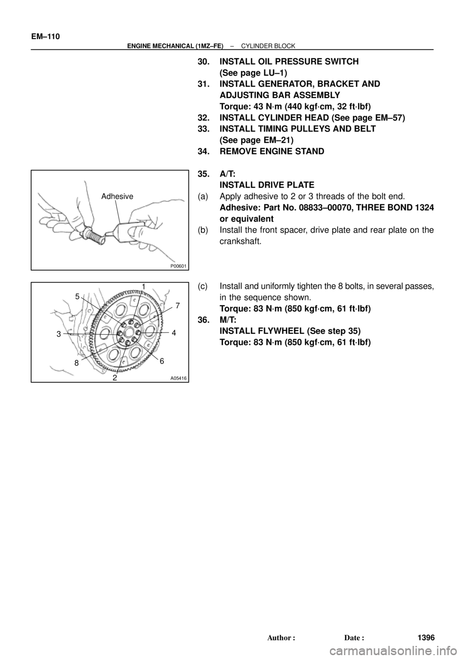
35. A/T:
INSTALL DRIVE PLATE
(a) Apply adhesive to 2 or 3 threads of the bolt end.
Adhesive: Part No. 08833±00070, THREE BOND 1324
or equivalent
(b) Install the front spacer, drive plate and rear plate on the
crankshaft.
(c) Install and uniformly tighten the 8 bolts, in several passes,
in the sequence shown.
Torque: 83 N´m (850 kgf´cm, 61 ft´lbf)
36. M/T:
INSTALL FLYWHEEL (See step 35)
Torque: 83 N´m (850 kgf´cm, 61 ft´lbf)
Page 2776 of 4592
EM0YU±01
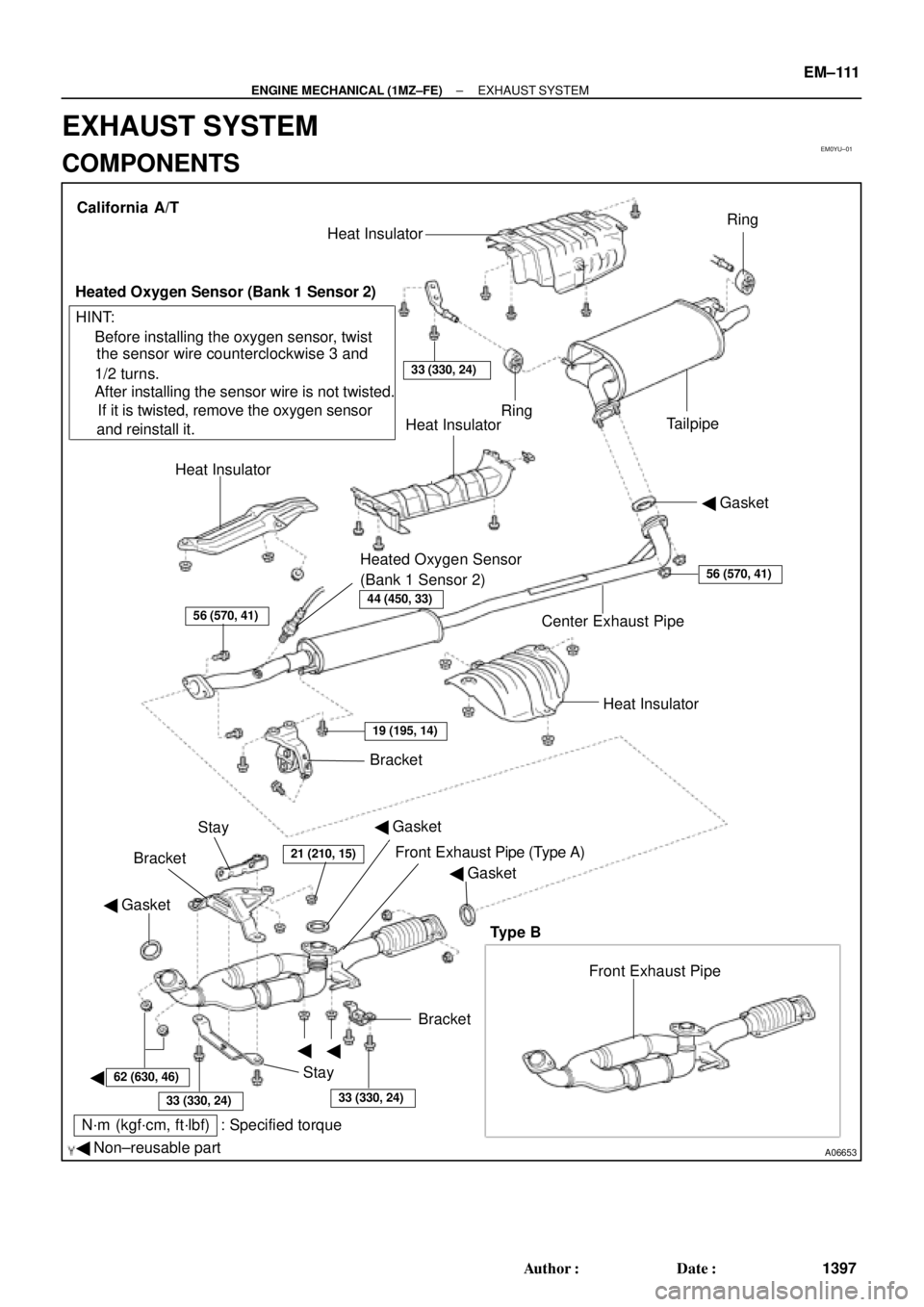
A06653
� Gasket
� Non±reusable part
N´m (kgf´cm, ft´lbf) : Specified torque� Gasket
�
�
�BracketFront Exhaust Pipe Bracket
StayHeat Insulator Center Exhaust Pipe� Gasket Heat InsulatorHeat Insulator
Heated Oxygen Sensor
(Bank 1 Sensor 2)TailpipeRing
Ring
33 (330, 24)
Heat Insulator
Heated Oxygen Sensor (Bank 1 Sensor 2)
� Before installing the oxygen sensor, twist
the sensor wire counterclockwise 3 and
1/2 turns.
If it is twisted, remove the oxygen sensor
and reinstall it. � After installing the sensor wire is not twisted. California A/T
Bracket
HINT:
56 (570, 41)
19 (195, 14)
21 (210, 15)
62 (630, 46)
33 (330, 24)33 (330, 24)
56 (570, 41)
Stay
Front Exhaust Pipe (Type A)
Type B
44 (450, 33)
� Gasket
± ENGINE MECHANICAL (1MZ±FE)EXHAUST SYSTEM
EM±111
1397 Author�: Date�:
EXHAUST SYSTEM
COMPONENTS
Page 2777 of 4592
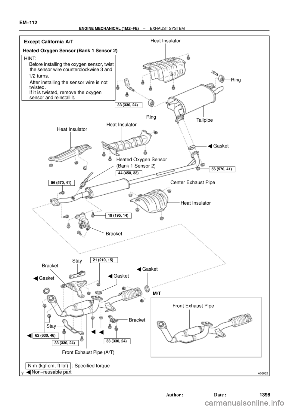
A06652
� Gasket
� Non±reusable part
N´m (kgf´cm, ft´lbf) : Specified torque� Gasket
�
�� Gasket
�Bracket
Stay
Front Exhaust Pipe (A/T) BracketBracket
Stay
21 (210, 15)
Heat Insulator Center Exhaust Pipe� Gasket Heat InsulatorHeat Insulator
Heated Oxygen Sensor
(Bank 1 Sensor 2)TailpipeRing
Ring
33 (330, 24)
Heat Insulator
Heated Oxygen Sensor (Bank 1 Sensor 2)
� Before installing the oxygen sensor, twist
the sensor wire counterclockwise 3 and
1/2 turns.
If it is twisted, remove the oxygen
sensor and reinstall it. � After installing the sensor wire is notExcept California A/T
HINT:
56 (570, 41)
19 (195, 14)
62 (630, 46)
33 (330, 24)33 (330, 24)
56 (570, 41)
twisted.
Front Exhaust Pipe
M/T
44 (450, 33)
EM±112
± ENGINE MECHANICAL (1MZ±FE)EXHAUST SYSTEM
1398 Author�: Date�:
Page 2780 of 4592
IGNITION SYSTEM
IG±3
1685 Author�: Date�:
(c) Using a 16 mm plug wrench, remove the 4 spark plugs.
(d) Visually check the sp")
S05308
16 mm Plug
Wrench
P20584
IG0152
B06373
Ohmmeter
± IGNITION (5S±FE)IGNITION SYSTEM
IG±3
1685 Author�: Date�:
(c) Using a 16 mm plug wrench, remove the 4 spark plugs.
(d) Visually check the spark plug for thread damage and insu-
lator damage.
If abnormal, replace the spark plug.
Recommended spark plug:
DENSO madePK20TR11
NGK madeBKR6EKPB11
(e) Inspect the electrode gaps.
Maximum electrode gap for used spark plug:
1.3 mm (0.051 in.)
If the gap is greater than maximum, replace the spark plug.
Correct electrode gap for new spark plug:
1.1 mm (0.043 in.)
NOTICE:
If adjusting the gap of a new spark plug, bend only the base
of the ground electrode. Do not touch the tip. Never attempt
to adjust the gap on the used plug.
(f) Clean the spark plugs.
If the electrode has traces of wet carbon, allow it to dry and then
clean with a spark plug cleaner.
Air pressure: Below 588 kPa (6 kgf/cm
2, 85 psi)
Duration: 20 seconds or less
HINT:
If there are traces of oil, remove it with gasoline before using the
spark plug cleaner.
(g) Using a 16 mm plug wrench, install the 4 spark plugs.
Torque: 18 N´m (180 kgf´cm, 13 ft´lbf)
(h) Reconnect the high±tension cords from the spark plugs.
4. INSPECT IGNITION COILS WITH IGNITERS
(a) Disconnect the high±tension cords from the ignition coils.
(b) Inspect the secondary coil resistance.
Using an ohmmeter, measure the resistance between the
high±tension terminals.
Secondary coil resistance:
Cold9.7 ± 16.7 kW
Hot12.4 ± 19.6 kW
Page 2782 of 4592
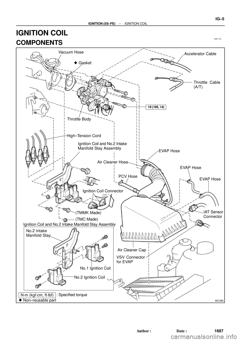
IG041±03
B01286
Vacuum Hose
� GasketAccelerator Cable
Throttle Cable
(A/T)
Throttle Body
High±Tension Cord
Ignition Coil and No.2 Intake
Manifold Stay Assembly
EVAP Hose
Air Cleaner Hose
IAT Sensor
Connector PCV Hose
VSV Connector
for EVAP
No.2 Ignition CoilNo.1 Ignition Coil No.2 Intake
Manifold Stay
N´m (kgf´cm, ft´lbf): Specified torque
� Non±reusable part
19 (195, 14)
EVAP Hose
EVAP Hose
Ignition Coil Connector
Air Cleaner Cap Ignition Coil and No.2 Intake Manifold Stay Assembly
(TMMK Made)
(TMC Made)
± IGNITION (5S±FE)IGNITION COIL
IG±5
1687 Author�: Date�:
IGNITION COIL
COMPONENTS
Page 2783 of 4592
IGNITION COIL
1688 Author�: Date�:
REPLACEMENT
1. DISCONNECT THROTTLE BODY FROM INTAKE MAN-
IFOLD (See page SF±32)
2. REMOVE IGN")
IG0DC±01
S05549
Wire
Clamp
S05604
No.1
No.2 IG±6
± IGNITION (5S±FE)IGNITION COIL
1688 Author�: Date�:
REPLACEMENT
1. DISCONNECT THROTTLE BODY FROM INTAKE MAN-
IFOLD (See page SF±32)
2. REMOVE IGNITION COILS AND NO.2 INTAKE MAN-
IFOLD STAY ASSEMBLY
(a) Disconnect the 2 ignition coil connectors.
(b) Disconnect the wire clamp from the manifold stay.
(c) TMC Made:
Remove the 2 nuts, 2 bolts, 2 ignition coils and manifold
stay assembly.
(d) TMMK Made:
Remove the nut, 3 bolts, 2 ignition coils and manifold stay
assembly.
3. REMOVE IGNITION COILS FROM NO.2 INTAKE MAN-
IFOLD STAY
Remove the 2 bolts and ignition coil. Remove the 2 ignition
coils.
4. REINSTALL IGNITION COILS TO NO.2 INTAKE MAN-
IFOLD STAY
Install the ignition coil with the 2 bolts. Install the 2 ignition coils.
Torque: 9.8 N´m (100 kgf´cm, 87 in.´lbf)
NOTICE:
The installation positions of the ignition coils are different
for No.1 and No.2.
5. REINSTALL IGNITION COILS AND NO.2 INTAKE MAN-
IFOLD STAY ASSEMBLY
(a) TMC Made:
Install the 2 ignition coils and manifold stay assembly with
the 2 nuts and 2 bolts.
(b) TMMK Made:
Install the 2 ignition coils and manifold stay assembly with
the nut and 3 bolts.
Torque:
21 N´m (214 kgf´cm, 15 ft´lbf) for 12 mm head
42 N´m (428 kgf´cm, 31 ft´lbf) for 14 mm head
(c) Install the wire clamp to the manifold stay.
(d) Connect the 2 ignition coil connectors.