Page 2695 of 4592
Engine Wire
 ProtectorEngine Wire
Protector
Heated Oxygen Sensor
(Bank 1 Sensor 1)
Connector
RH Exhaust Manifold
(Except")
A06635� Non±reusable part: Specified torque
N´m (kgf´cm, ft´lbf)Engine Wire
Engine Wire ProtectorEngine Wire
Protector
Heated Oxygen Sensor
(Bank 1 Sensor 1)
Connector
RH Exhaust Manifold
(Except M/T and California A/T)
34 (350,25)
x 6
12 (120, 9)
PS Pump Bracket
43 (440, 32)
No.1 EGR Pipe � Gasket
Cylinder Head Rear Plate
Ground Strap
Water Inlet
Pipe � O±Ring
Gasket
20 (200, 14)
CollarBushing No.3 Timing
Belt Cover
x 6
x 6
� O±Ring
49 (500, 36)LH Exhaust
Manifold Stay
(Except M/T and
California A/T ) Oil Dipstick Guide Engine WireRH Exhaust Manifold
RH Exhaust
Manifold Stay
� Gasket
20 (200, 14)
Heated Oxygen Sensor
(Bank 2 Sensor 1)
Connector
34 (350,25)
49 (500, 36)
LH Exhaust
Manifold Stay
LH Exhaust Manifold
California A/T
M/T and California A/T
� Gasket
Camshaft
Position Sensor
ConnectorGasket RH
Exhaust
Manifold
Stay
(Except M/T and Calif. A/T)
Camshaft Position Sensor
LH Exhaust Manifold
(Except California A/T)
49 (500, 36)
x 6 EM±30
± ENGINE MECHANICAL (1MZ±FE)CYLINDER HEAD
1316 Author�: Date�:
Page 2696 of 4592
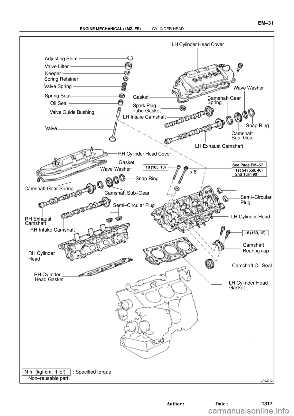
A02013
Adjusting Shim
Valve Lifter
Keeper
Spring Retainer
Valve Spring
Spring Seat
� Oil Seal
Valve � Valve Guide BushingLH Cylinder Head Cover
GasketWave Washer
Camshaft Gear
Spring
� Spark Plug
Tube Gasket
LH Intake Camshaft
Snap Ring
Camshaft
Sub±Gear
LH Exhaust Camshaft
RH Cylinder Head Cover
Gasket
RH Intake CamshaftCamshaft Sub±GearSnap Ring
Camshaft Gear Spring
RH Exhaust
CamshaftWave Washer
Semi±Circular PlugSemi±Circular
Plug
LH Cylinder Head
Camshaft
Bearing cap
� Camshaft Oil Seal RH Cylinder
Head
� RH Cylinder
Head Gasket
� LH Cylinder Head
Gasket x 8
N´m (kgf´cm, ft´lbf) : Specified torque
� Non±reusable part
18 (185, 13)
16 (160, 12) See Page EM±57
1st 54 (550, 40)
2nd Turn 90°
± ENGINE MECHANICAL (1MZ±FE)CYLINDER HEAD
EM±31
1317 Author�: Date�:
Page 2714 of 4592
CYLINDER HEAD
EM±49
1335 Author�: Date�:
17. INSPECT CAMSHAFT JOURNAL OIL CLEARANCE
(a) Clean the bearing caps and camshaft journa")
P13009
Plastigage
P12892
P13004
P12891
± ENGINE MECHANICAL (1MZ±FE)CYLINDER HEAD
EM±49
1335 Author�: Date�:
17. INSPECT CAMSHAFT JOURNAL OIL CLEARANCE
(a) Clean the bearing caps and camshaft journals.
(b) Place the camshafts on the cylinder head.
(c) Lay a strip of Plastigage across each of the camshaft jour-
nal.
(d) Install the bearing caps. (See page EM±57)
Torque: 16 N´m (160 kgf´cm, 12 ft´lbf)
NOTICE:
Do not turn the camshaft.
(e) Remove the bearing caps.
(f) Measure the Plastigage at its widest point.
Standard oil clearance:
Intake0.035 ± 0.072 mm (0.0014 ± 0.0028 in.)
Exhaust0.025 ± 0.062 mm (0.0010 ± 0.0024 in.)
Maximum oil clearance:
Intake0.10 mm (0.0039 in.)
Exhaust0.09 mm (0.0035 in.)
If the oil clearance is greater than maximum, replace the cam-
shaft. If necessary, replace the bearing caps and cylinder head
as a set.
(g) Completely remove the Plastigage.
(h) Remove the camshafts.
18. INSPECT CAMSHAFT THRUST CLEARANCE
(a) Install the camshafts. (See page EM±57)
(b) Using a dial indicator, measure the thrust clearance while
moving the camshaft back and forth.
Standard thrust clearance:
0.040 ± 0.090 mm (0.0016 ± 0.0035 in.)
Maximum thrust clearance: 0.12 mm (0.0047 in.)
If the thrust clearance is greater than maximum, replace the
camshaft. If necessary, replace the bearing caps and cylinder
head as a set.
Page 2722 of 4592
CYLINDER HEAD
EM±57
1343 Author�: Date�:
INSTALLATION
1. PLACE C")
EM0YR±01
P12393
P12736
12 Pointed Head Bolt
Front7246
5318
7246 5318
P25742
Painted Mark
90°
Front90°
± ENGINE MECHANICAL (1MZ±FE)CYLINDER HEAD
EM±57
1343 Author�: Date�:
INSTALLATION
1. PLACE CYLINDER HEAD ON CYLINDER BLOCK
(a) Place 2 new cylinder head gaskets in position on the cylin-
der block.
NOTICE:
Be careful of the installation direction.
(b) Place the 2 cylinder heads in position on the cylinder head
gaskets.
2. INSTALL 12 POINTED HEAD CYLINDER HEAD BOLTS
HINT:
�The cylinder head bolts are tightened in 2 progressive
steps (steps (c) and (e)).
�If any bolt is broken or deformed, replace it.
(a) Apply a light coat of engine oil on the threads and under
the heads of the cylinder head bolts.
(b) Install the plate washer to the cylinder head bolt.
(c) Install and uniformly tighten the cylinder head bolts on
each cylinder head, in several passes, in the sequence
shown, then repeat for the other side, as shown.
Torque: 54 N´m (550 kgf´cm, 40 ft´lbf)
If any of the cylinder head bolts does not meet the torque speci-
fication, replace the cylinder head bolt.
(d) Mark the front of the cylinder head bolt head with paint.
(e) Retighten the cylinder head bolts by 90° in the numerical
order shown.
(f) Check that the painted mark is now at a 90° angle to the
front.
Page 2723 of 4592
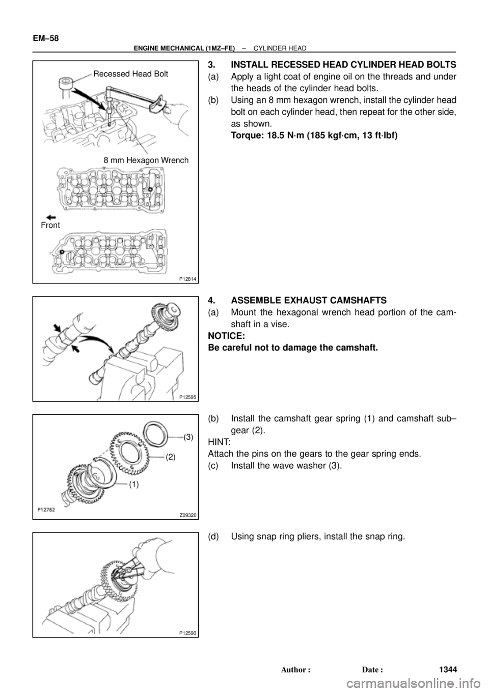
P12814
Recessed Head Bolt
8 mm Hexagon Wrench
Front
P12595
Z09320
(3)
(2)
(1)
P12590
EM±58
± ENGINE MECHANICAL (1MZ±FE)CYLINDER HEAD
1344 Author�: Date�:
3. INSTALL RECESSED HEAD CYLINDER HEAD BOLTS
(a) Apply a light coat of engine oil on the threads and under
the heads of the cylinder head bolts.
(b) Using an 8 mm hexagon wrench, install the cylinder head
bolt on each cylinder head, then repeat for the other side,
as shown.
Torque: 18.5 N´m (185 kgf´cm, 13 ft´lbf)
4. ASSEMBLE EXHAUST CAMSHAFTS
(a) Mount the hexagonal wrench head portion of the cam-
shaft in a vise.
NOTICE:
Be careful not to damage the camshaft.
(b) Install the camshaft gear spring (1) and camshaft sub±
gear (2).
HINT:
Attach the pins on the gears to the gear spring ends.
(c) Install the wave washer (3).
(d) Using snap ring pliers, install the snap ring.
Page 2725 of 4592
CYLINDER HEAD
1346 Author�: Date�:
(b) Install th")
P12890
Exhaust
P12887
Exhaust
8
76
5
4
32
19 10
P12875
Intake
Align
P12798
Intake
P25422
Intake
8 76 5
4 32 19
10
EM±60
± ENGINE MECHANICAL (1MZ±FE)CYLINDER HEAD
1346 Author�: Date�:
(b) Install the 5 bearing caps in their proper locations.
(c) Apply a light coat of engine oil on the threads and under
the heads of the bearing cap bolts.
(d) Install and uniformly tighten the 10 bearing cap bolts, in
several passes, in the sequence shown.
Torque: 16 N´m (160 kgf´cm, 12 ft´lbf)
(e) Install the Intake camshaft.
(1) Apply new engine oil to the thrust portion and jour-
nal of the camshaft.
(2) Align the timing marks (2 dot marks) of the camshaft
drive and driven gears.
(3) Place the intake camshaft on the cylinder head.
(4) Install the 5 bearing caps in their proper locations.
(5) Apply a light coat of engine oil on the threads and
under the heads of the bearing cap bolts.
(6) Install and uniformly tighten the 10 bearing cap
bolts, in several passes, in the sequence shown.
Torque: 16 N´m (160 kgf´cm, 12 ft´lbf)
Page 2727 of 4592
CYLINDER HEAD
1348 Author�: Date�:
(7) Install t")
P12962
Exhaust
P25421
Exhaust
86 5
4 32 19
10
7
P12874
Intake
Align
P12961
Intake
P12959
Intake
6
5
4
32
19 10
7 8 EM±62
± ENGINE MECHANICAL (1MZ±FE)CYLINDER HEAD
1348 Author�: Date�:
(7) Install the 5 bearing caps in their proper locations.
(8) Apply a light coat of engine oil on the threads and
under the heads of the bearing cap bolts.
(9) Install and uniformly tighten the 10 bearing cap
bolts, in several passes, in the sequence shown.
Torque: 16 N´m (160 kgf´cm, 12 ft´lbf)
(b) Install the intake camshaft.
(1) Apply new engine oil to the thrust portion and jour-
nal of the camshaft.
(2) Align the timing marks (1 dot mark) of the camshaft
drive and driven gears.
(3) Place the intake camshaft on the cylinder head.
(4) Install the 5 bearing caps in their proper locations.
(5) Apply a light coat of engine oil on the threads and
under the heads of bearing cap bolts.
(6) Install and uniformly tighten the 10 bearing cap
bolts, in several passes, in the sequence shown.
Torque: 16 N´m (160 kgf´cm, 12 ft´lbf)
Page 2729 of 4592
CYLINDER HEAD
1350 Author")
P12812
: Seal Packing
Front
RH Side
LH Side
A06649
Manifold
StayM/T and California A/T
Manifold
Stay
Except M/T and California A/T
P18773
EM±64
± ENGINE MECHANICAL (1MZ±FE)CYLINDER HEAD
1350 Author�: Date�:
9. INSTALL CYLINDER HEAD COVERS
(a) Apply seal packing to the cylinder heads as shown in the
illustration.
Seal packing: Part No. 08826±00080 or equivalent
(b) Install the gasket to the cylinder head cover.
(c) Install the cylinder head cover with the 8 bolts. Uniformly
tighten the bolts in several passes. Install the 2 cylinder
head covers.
Torque: 8 N´m (80 kgf´cm, 69 in.´lbf)
10. INSTALL RH EXHAUST MANIFOLD
(a) Install a new gasket and the exhaust manifold with the 6
nuts. Uniformly tighten the nuts in several passes.
Torque: 49 N´m (500 kgf´cm, 36 ft´lbf)
(b) Install the exhaust manifold stay with the bolt and nut. Al-
ternately tighten the bolt and nut.
Torque:
M/T and California A/T
34 N´m (350 kgf´cm, 25 ft´lbf)
Except M/T and California A/T:
20 N´m (200 kgf´cm, 15 ft´lbf)
(c) California:
Connect the A/F sensor connector.
(d) Except California:
Connect the heated oxygen sensor (bank 1 sensor 1)
connector.
11. INSTALL NO.1 EGR PIPE
Install 2 new gaskets and the EGR pipe with the 4 nuts.
Torque: 12 N´m (120 kgf´cm, 9 ft´lbf)
12. INSTALL PS PUMP BRACKET
Torque: 43 N´m (440 kgf´cm, 32 ft´lbf)