Page 2730 of 4592
Except California A/T
S04789
Ground
Strap
Inlet PipeRear
Plate
± ENGINE MECHANICAL (1MZ±FE)CYLINDER HEAD
EM±65
1351")
P12710
New O±Ring
A01522
Manifold
Stay California A/T
Manifold Stay
(Except M/T)Except California A/T
S04789
Ground
Strap
Inlet PipeRear
Plate
± ENGINE MECHANICAL (1MZ±FE)CYLINDER HEAD
EM±65
1351 Author�: Date�:
13. INSTALL OIL DIPSTICK AND GUIDE
(a) Install a new O±ring to the dipstick guide.
(b) Apply soapy water to the O±ring.
(c) Push in the dipstick guide end into the guide hole of the
No.1 oil pan.
(d) Install the dipstick guide with the bolt.
Torque: 8 N´m (80 kgf´cm, 69 in.´lbf)
(e) Install the dipstick.
14. INSTALL CAMSHAFT POSITION SENSOR
15. INSTALL LH EXHAUST MANIFOLD
(a) Install a new gasket and the exhaust manifold with the 6
nuts. Uniformly tighten the nuts in several passes.
Torque: 49 N´m (500 kgf´cm, 36 ft´lbf)
(b) Except M/T:
Install the exhaust manifold stay with the bolt and nut. Al-
ternately tighten the bolt and nut.
Torque:
California A/T:
34 N´m (350 kgf´cm, 25 ft´lbf)
Except California A/T:
20 N´m (200 kgf´cm, 15 ft´lbf)
(c) California:
Connect the A/F sensor connector.
(d) Except California:
Connect the heated oxygen sensor (bank 2 sensor 1)
connector.
16. INSTALL WATER INLET PIPE
(a) Install a new O±ring to the water inlet pipe.
(b) Apply soapy water to the O±ring.
(c) Connect the water inlet pipe to the water inlet.
(d) Install the bolt holding the water inlet pipe to the cylinder
head.
Torque: 19.5 N´m (200 kgf´cm, 14 ft´lbf)
17. INSTALL CYLINDER HEAD REAR PLATE
Torque: 8 N´m (80 kgf´cm, 69 in.´lbf)
18. INSTALL ENGINE WIRE PROTECTOR
19. INSTALL NO.3 TIMING BELT COVER
(a) Check that the timing belt cover gaskets have no cracks
or peeling, etc.
If the gaskets have cracks or peeling etc., replace them using
these steps:
�Using a screwdriver and gasket scraper, remove all
the old gasket material.
�Thoroughly clean all components to remove all the
loose material.
Page 2731 of 4592

L = 180 mm (7.09 in.)L = 72 mm (2.83 in.)
L = 335 mm (13.19 in.)L = 180 mm
(7.09 in.)
L = Length Join
LineJoin
Line
Z14262New Gasket
A01808
8
6
5
4
3
2
1
9
10
7
11
EM")
A05194
L = 133 mm (5.24 in.)
L = 180 mm (7.09 in.)L = 72 mm (2.83 in.)
L = 335 mm (13.19 in.)L = 180 mm
(7.09 in.)
L = Length Join
LineJoin
Line
Z14262New Gasket
A01808
8
6
5
4
3
2
1
9
10
7
11
EM±66
± ENGINE MECHANICAL (1MZ±FE)CYLINDER HEAD
1352 Author�: Date�: �
Remove the backing paper from a new gasket and
install the gasket evenly to the part of the timing belt
cover shaded black in the illustration.
NOTICE:
When joining 2 gaskets, do not leave a gap between them.
Cut off any excess gasket.
�After installing the gasket, press down on it so that
the adhesive firmly sticks to the timing belt cover.
(b) Install the timing belt cover with the 6 bolts.
Torque: 8.5 N´m (85 kgf´cm, 74 in.´lbf)
(c) Install the 3 engine wire clamps to the timing belt cover.
20. INSTALL NO.2 IDLER PULLEY (See page EM±21)
21. INSTALL CAMSHAFT TIMING PULLEYS
(See page EM±21)
22. INSTALL TIMING BELT (See page EM±21)
23. INSTALL SPARK PLUGS
24. INSTALL IGNITION COILS
25. INSTALL PS PUMP DRIVE BELT
26. INSTALL GENERATOR DRIVE BELT
(See page SR±28)
27. INSTALL WATER OUTLET
(a) Install 2 new gaskets.
(b) Connect the water outlet to the bypass hose.
(c) Install the water outlet with the 2 bolts, 2 nuts and 2 plate
washers. Alternately tighten the bolts and nuts.
Torque: 15 N´m (150 kgf´cm, 11 ft´lbf)
NOTICE:
Do not scratch the seal surface of the water outlet with the
stud bolt.
(d) Connect the ECT sender gauge connector.
(e) Connect the ECT sensor connector.
(f) Connect the ground strap (connector).
(g) Connect the radiator hose.
(h) Connect the engine coolant reservoir hose.
28. INSTALL INTAKE MANIFOLD ASSEMBLY
(a) Install the intake manifold, delivery pipe and injectors as-
sembly with the 9 bolts, 2 plate washers and 2 nuts. Uni-
formly tighten the bolts and nuts, in several passes, in the
sequence shown.
Torque: 15 N´m (150 kgf´cm, 11 ft´lbf)
Page 2732 of 4592
CYLINDER HEAD
EM±67
1353 Author�: Date�:
(b) Connect the fuel inlet hose to the fuel filter.
CAUTI")
S04791
8 mm Hexagon
Wrench
S04790
Chamber Stay
Engine
Hanger EGR
Pipe
± ENGINE MECHANICAL (1MZ±FE)CYLINDER HEAD
EM±67
1353 Author�: Date�:
(b) Connect the fuel inlet hose to the fuel filter.
CAUTION:
Perform connecting operations of the fuel tube connector
(quick type) after observing the precaution.
(See page SF±1)
(c) Connect the heater hose to the intake manifold.
29. RETIGHTEN WATER OUTLET MOUNTING BOLTS
AND NUTS
Tighten the 2 bolts and 2 nuts.
Torque: 15 N´m (150 kgf´cm, 11 ft´lbf)
30. INSTALL AIR INTAKE CHAMBER ASSEMBLY
(a) Using an 8 mm hexagon wrench, install a new gasket and
the air intake chamber assembly with the 2 bolts and 2
nuts. Uniformly tighten the bolts and nuts in several
passes.
Torque: 43 N´m (440 kgf´cm, 32 ft´lbf)
(b) Install 2 new gaskets and No.2 EGR pipe with the 4 nuts.
Torque: 12 N´m (120 kgf´cm, 9 ft´lbf)
(c) Install the No.1 engine hanger with the 2 bolts.
Torque: 39 N´m (400 kgf´cm, 29 ft´lbf)
(d) Install the air intake chamber stay with the 2 bolts.
Torque: 19.5 N´m (200 kgf´cm, 14 ft´lbf)
(e) Connect the PCV hose to the PCV valve on the RH cylin-
der head.
(f) Connect the ground strap and cable to the intake air con-
trol valve for the ACIS.
(g) Connect the ground cable and strap with the nut.
Torque: 14.5 N´m (145 kgf´cm, 10 ft´lbf)
(h) Connect the ground cable to the air intake chamber.
(i) Connect the brake booster vacuum hose to the air intake
chamber.
(j) Connect the 2 water bypass hoses to the throttle body.
(k) Connect the air assist hose to the throttle body.
(l) Connect the purge hose to the emission control valve set.
(m) Connect the 2 vacuum hoses to the vacuum tank for the
ACIS.
(n) Connect the engine wire clamp to the emission control
valve set.
(o) Install the PS pressure tube with the 2 nuts.
(p) Connect the throttle position sensor connector.
(q) Connect the IAC valve connector.
(r) Connect the EGR gas temperature sensor connector.
(s) Connect the EGR valve position sensor connector.
(t) Connect the VSV connector for the ACIS.
(u) Connect the VSV connecter for the EVAP.
(v) Connect the VSV connector for the EGR.
Page 2734 of 4592

EM04X±04
A06650
No.2 Cooling Fan Connector
Upper Radiator Support
Radiator Assembly
RH Fender
Apron
Seal
Generator
Drive
Belt
A/C Compressor
ConnectorNo.1 ECT Switch
Wire Connector
Battery
Insulator
Battery
Battery
Tray Generator Drive
Belt Adjusting
Bar Bracket
LH Fender
Apron SealA/T
Oil Cooler
Hose
� Gasket A/C Compressor
43 (440, 32)
25 (250, 18)
�Non±reusable partStay
N´m (kgf´cm, ft´lbf)Bracket Front Exhaust Pipe: Specified torque� Gasket
62 (630, 46)
33 (330, 24)
�
62 (630, 46)
33 (330, 24)
� Gasket
56 (570, 41)
Actuator Cover
EGR Vacuum HoseUpper Radiator
Support
No.1 Cooling
Fan ConnectorHood
Hold±Down
Clamp
Washer
Hose for
Windshield
Air Filter
Air Cleaner Case
� O±Ring Lower Radiator Support
Drain
Plug
Lower Radiator
Support
Air Cleaner
Cap Assembly
Radiator Upper Hose
Cruise Control
Actuator
Cruise Control
Actuator
Connector
Accelerator Cable
PS Pump
Radiator Lower Hose
� PS Pump
Drive Belt
EVAP Hose
MAF Meter
Connector
± ENGINE MECHANICAL (1MZ±FE)ENGINE UNIT
EM±69
1355 Author�: Date�:
ENGINE UNIT
COMPONENTS
Page 2735 of 4592
A06646
RH Drive Shaft
LH Drive Shaft
Tie Rod End
49 (500, 36)
294 (3,000, 217)64 (650, 47)32 (320, 23)
RH Engine
Mounting Stay
Lower Suspension Arm Engine Moving
Control Rod
64 (650, 47)
127 (1,300, 94)
No.2 RH Engine
Mounting Stay (M/T)
No.2 RH Engine
Mounting Bracket
Engine and Transaxle
Assembly
64 (650, 47)
66 (670, 48)
64 (650, 47)
Front Engine
Mounting Insulator
48 (490, 35)
64 (650, 47)
Transaxle
Control Cable
Engine Mounting Absorber
TMC Made 80 (820,59)
TMMK Made
Green Clolr Bolt 66 (670, 48)
Silver Clolr Bolt 44 (450,32)
N´m (kgf´cm, ft´lbf) : Specified torque
� Non±reusable part�
Rear Engine
Mounting
Insulator
EM±70
± ENGINE MECHANICAL (1MZ±FE)ENGINE UNIT
1356 Author�: Date�:
Page 2739 of 4592
P18755
P19478
Engine
Hanger
S04501
S05451
EM±74
± ENGINE MECHANICAL (1MZ±FE)ENGINE UNIT
1360 Author�: Date�:
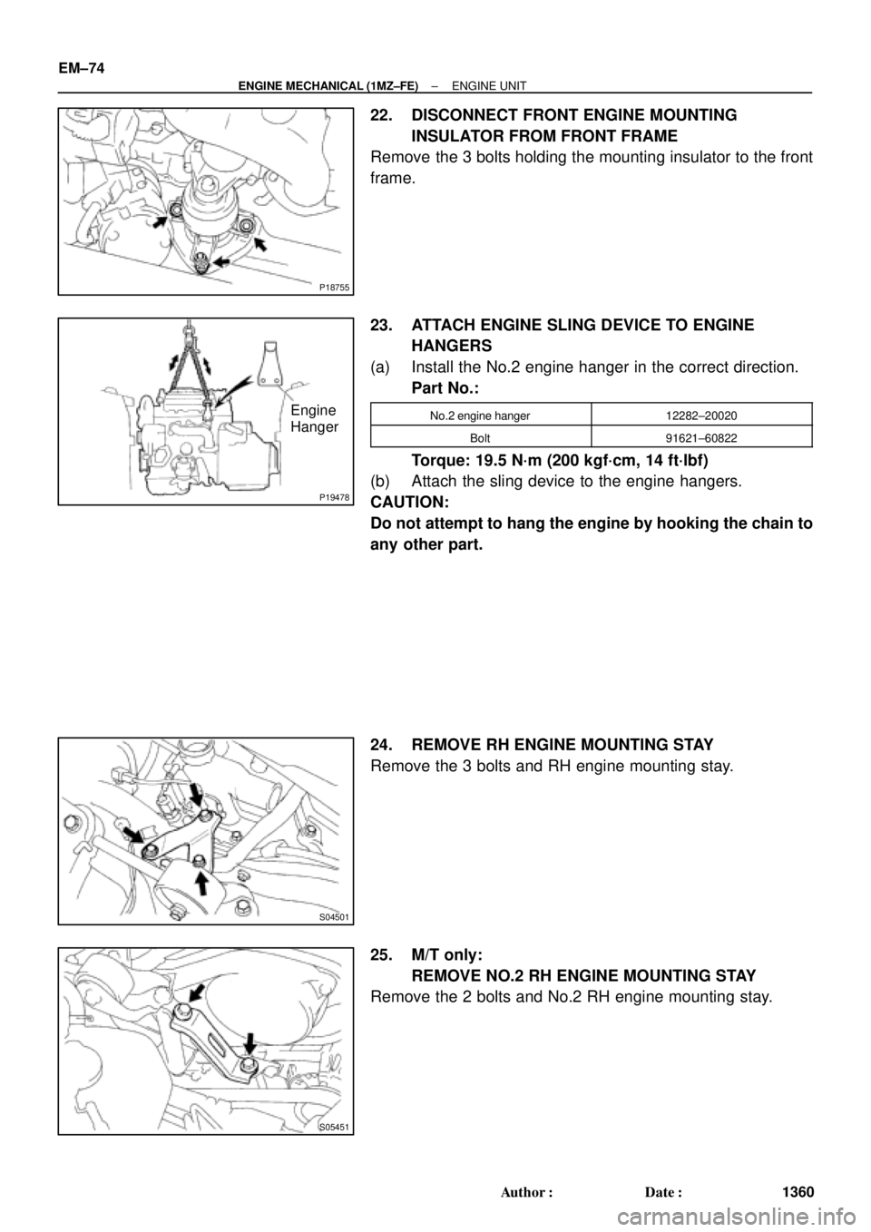
22. DISCONNECT FRONT ENGINE MOUNTING
INSULATOR FROM FRONT FRAME
Remove the 3 bolts holding the mounting insulator to the front
frame.
23. ATTACH ENGINE SLING DEVICE TO ENGINE
HANGERS
(a) Install the No.2 engine hanger in the correct direction.
Part No.:
No.2 engine hanger12282±20020
Bolt91621±60822
Torque: 19.5 N´m (200 kgf´cm, 14 ft´lbf)
(b) Attach the sling device to the engine hangers.
CAUTION:
Do not attempt to hang the engine by hooking the chain to
any other part.
24. REMOVE RH ENGINE MOUNTING STAY
Remove the 3 bolts and RH engine mounting stay.
25. M/T only:
REMOVE NO.2 RH ENGINE MOUNTING STAY
Remove the 2 bolts and No.2 RH engine mounting stay.
Page 2741 of 4592
ENGINE UNIT
1362 Author�: Date�:
INSTALLATION
1. ASSEMBLE ENGINE AND TRANSAXLE
E153 M/T (See page MX±4)
A541E A/T (See")
EM04Z±04
S04992
Lower
S04754
S05451
S04501
EM±76
± ENGINE MECHANICAL (1MZ±FE)ENGINE UNIT
1362 Author�: Date�:
INSTALLATION
1. ASSEMBLE ENGINE AND TRANSAXLE
E153 M/T (See page MX±4)
A541E A/T (See page AX±23)
2. INSTALL REAR ENGINE MOUNTING INSULATOR
Install the mounting insulator with the 4 bolts.
Torque: 64 N´m (650 kgf´cm, 47 ft´lbf)
3. INSTALL FRONT ENGINE MOUNTING INSULATOR
Install the mounting insulator with the 4 bolts.
Torque: 64 N´m (650 kgf´cm, 47 ft´lbf)
4. INSTALL ENGINE AND TRANSAXLE ASSEMBLY IN
VEHICLE
(a) Attach the engine sling device to the engine hangers.
(b) Lower the engine into the engine compartment.
Tilt the transaxle downward, lower the engine and clear
the LH mounting.
NOTICE:
Be careful not to hit the park/neutral position switch.
(c) Keep the engine level, and align RH and LH mountings
with the body bracket.
5. INSTALL NO.2 RH ENGINE MOUNTING BRACKET
AND ENGINE MOVING CONTROL ROD
Install the mounting moving control rod and No.2 RH engine
mounting bracket with the 3 bolts.
Torque: 64 N´m (650 kgf´cm, 47 ft´lbf)
6. M/T only:
INSTALL NO.2 RH ENGINE MOUNTING STAY
Install the No.2 RH engine mounting stay with the 2 bolts.
Torque: 64 N´m (650 kgf´cm, 47 ft´lbf)
7. INSTALL RH ENGINE MOUNTING STAY
Install the RH mounting stay with the 3 bolts.
Torque: 32 N´m (320 kgf´cm, 23 ft´lbf)
Page 2742 of 4592
P18755
A05426
P18752
S05393
M/T
Z18907
A/T
± ENGINE MECHANICAL (1MZ±FE)ENGINE UNIT
EM±77
1363 Author�: Date�:
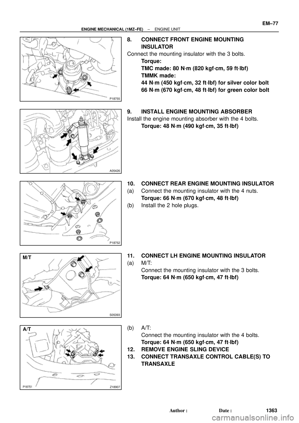
8. CONNECT FRONT ENGINE MOUNTING
INSULATOR
Connect the mounting insulator with the 3 bolts.
Torque:
TMC made: 80 N´m (820 kgf´cm, 59 ft´lbf)
TMMK made:
44 N´m (450 kgf´cm, 32 ft´lbf) for silver color bolt
66 N´m (670 kgf´cm, 48 ft´lbf) for green color bolt
9. INSTALL ENGINE MOUNTING ABSORBER
Install the engine mounting absorber with the 4 bolts.
Torque: 48 N´m (490 kgf´cm, 35 ft´lbf)
10. CONNECT REAR ENGINE MOUNTING INSULATOR
(a) Connect the mounting insulator with the 4 nuts.
Torque: 66 N´m (670 kgf´cm, 48 ft´lbf)
(b) Install the 2 hole plugs.
11. CONNECT LH ENGINE MOUNTING INSULATOR
(a) M/T:
Connect the mounting insulator with the 3 bolts.
Torque: 64 N´m (650 kgf´cm, 47 ft´lbf)
(b) A/T:
Connect the mounting insulator with the 4 bolts.
Torque: 64 N´m (650 kgf´cm, 47 ft´lbf)
12. REMOVE ENGINE SLING DEVICE
13. CONNECT TRANSAXLE CONTROL CABLE(S) TO
TRANSAXLE

294 (3,000, 217)64 (650, 47)32 (320, 23)
RH Engine
Mounting Stay
Lower Suspension Arm Engine Moving
Control Rod
64 (650, 47)
127 (1,300, 9")