Page 2921 of 4592
P12694
LU±16
± LUBRICATION (1MZ±FE)OIL PUMP
1680 Author�: Date�:
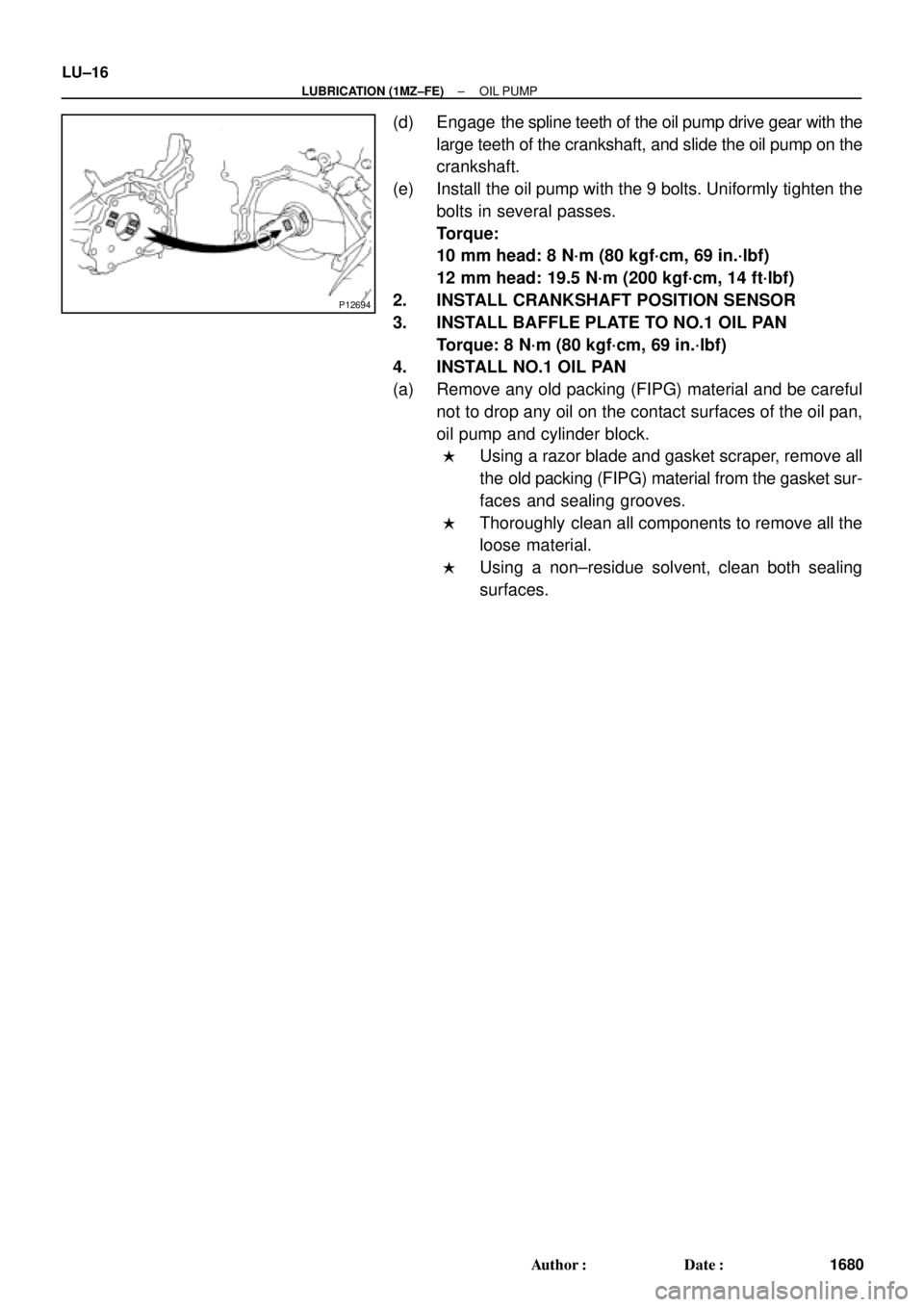
(d) Engage the spline teeth of the oil pump drive gear with the
large teeth of the crankshaft, and slide the oil pump on the
crankshaft.
(e) Install the oil pump with the 9 bolts. Uniformly tighten the
bolts in several passes.
Torque:
10 mm head: 8 N´m (80 kgf´cm, 69 in.´lbf)
12 mm head: 19.5 N´m (200 kgf´cm, 14 ft´lbf)
2. INSTALL CRANKSHAFT POSITION SENSOR
3. INSTALL BAFFLE PLATE TO NO.1 OIL PAN
Torque: 8 N´m (80 kgf´cm, 69 in.´lbf)
4. INSTALL NO.1 OIL PAN
(a) Remove any old packing (FIPG) material and be careful
not to drop any oil on the contact surfaces of the oil pan,
oil pump and cylinder block.
�Using a razor blade and gasket scraper, remove all
the old packing (FIPG) material from the gasket sur-
faces and sealing grooves.
�Thoroughly clean all components to remove all the
loose material.
�Using a non±residue solvent, clean both sealing
surfaces.
Page 2922 of 4592
OIL PUMP
LU±17
1681 Author�: Date�:
(b) Appl")
B04402
A Region ºXºRegion ºYº
A
CB B
C
Seal Width
Type A: 4 ± 5 mm
Type B: 3 ± 4 mmRegion ºXºRegion ºYº
AC Type A
Type B
± LUBRICATION (1MZ±FE)OIL PUMP
LU±17
1681 Author�: Date�:
(b) Apply seal packing to the oil pan as shown in the illustra-
tion.
Seal packing: Part No. 08826±00080 or equivalent
Region ºXº is at the outer side of the bolt hole.
Region ºYº is at the inner side of the bolt hole.
�Install a nozzle that has been cut to a 4 ± 5 mm (0.16
± 0.20 in.) (Type A) or 3 ± 4 mm (0.12 ± 0.16 in.)
(Type B) opening.
HINT:
Avoid applying an excessive amount to the surface.
�Parts must be assembled within 3 minutes of ap-
plication. Otherwise the material must be removed
and reapplied.
�Immediately remove nozzle from the tube and rein-
stall cap.
(c) Install the oil pan with the 19 bolts (or 17 bolts and 2 nuts).
Uniformly tighten the bolts and nuts in several passes.
Torque:
10 mm head: 8 N´m (80 kgf´cm, 69 in.´lbf)
12 mm head: 19.5 N´m (200 kgf´cm, 14 ft´lbf)
14 mm head: 37.2 N´m (380 kgf´cm, 27 ft´lbf)
(d) Install the flywheel housing under cover and exhaust pipe
support stay with the 2 bolts.
Torque: 7.8 N´m (80 kgf´cm, 69 in.´lbf)
5. INSTALL OIL STRAINER
Install a new gasket and the oil strainer with the bolt and 2 nuts.
Torque: 8 N´m (80 kgf´cm, 69 in.´lbf)
6. INSTALL NO.2 OIL PAN
(a) Remove any old packing (FIPG) material and be careful
not to drop any oil on the contact surface of the No.1 and
No.2 oil pans.
�Using a razor blade and gasket scraper, remove all
the old packing (FIPG) material from the gasket sur-
faces and sealing grooves.
�Thoroughly clean all components to remove all the
loose material.
�Using a non±residue solvent, clean both sealing
surfaces.
NOTICE:
Do not use a solvent which will affect the painted surfaces.
Page 2923 of 4592
OIL PUMP
1682 Author�: Date�:
(b) Apply seal packing to the No.2 oil pan as shown in the il-
lustration.
Seal packing:
Part No. 08826�")
P12568
A
A
BB
Seal Width
4 ± 5 mm LU±18
± LUBRICATION (1MZ±FE)OIL PUMP
1682 Author�: Date�:
(b) Apply seal packing to the No.2 oil pan as shown in the il-
lustration.
Seal packing:
Part No. 08826±00080 or equivalent
�Install a nozzle that has been cut to a 4 ± 5 mm (0.16
± 0.20 in.) opening.
HINT:
Avoid applying an excessive amount to the surface.
�Parts must be assembled within 3 minutes of ap-
plication. Otherwise the material must be removed
and reapplied.
�Immediately remove nozzle from the tube and rein-
stall cap.
(c) Install the No.2 oil pan with the 10 bolts and 2 nuts. Uni-
formly tighten the bolts and nuts in several passes.
Torque: 8 N´m (80 kgf´cm, 69 in.´lbf)
7. INSTALL A/C COMPRESSOR HOUSING BRACKET
Torque: 25 N´m (250 kgf´cm, 18 ft´lbf)
8. INSTALL NO.3 TIMING BELT COVER
(See page EM±21)
9. INSTALL TIMING PULLEYS (See page EM±21)
10. INSTALL TIMING BELT (See page EM±21)
11. INSTALL ADJUSTING STRUT AND PS PUMP DRIVE
BELT
(a) Temporarily install the adjusting strut with the bolt and the
nut.
(b) Install the drive belt with the pivot and adjusting bolts.
Torque: 43.1 N´m (440 kgf´cm, 32 ft´lbf)
(c) Tighten the nut.
Torque: 43.1 N´m (440 kgf´cm, 32 ft´lbf)
12. INSTALL A/C COMPRESSOR (See page AC±47)
13. INSTALL GENERATOR DRIVE BELT
(See page CH±16)
14. INSTALL FRONT EXHAUST PIPE BRACKET TO
NO.1 OIL PAN
Torque: 21 N´m (210 kgf´cm, 15 ft´lbf)
15. INSTALL FRONT EXHAUST PIPE (See page EM±76)
16. REMOVE RH FENDER APRON SEAL
17. REMOVE RH FRONT WHEEL
18. FILL ENGINE WITH OIL
19. START ENGINE AND CHECK FOR LEAKS
20. RECHECK ENGINE OIL LEVEL
Page 2931 of 4592

MA0676B00995
MA00O±01
N21126
N21125
MA±8
± MAINTENANCEBODY
51 Author�: Date�:
BODY
INSPECTION
1. TIGHTEN BOLTS AND NUTS ON CHASSIS AND
BODY
Tighten these parts:
�Front seat mount bolts
Torque: 37 N´m (375 kgf´cm, 27 ft´lbf)
�Front suspension member±to±body mounting bolts
Torque: 181 N´m (1,850 kgf´cm, 134 ft´lbf)
�Rear suspension member±to±body mounting nuts
Torque: 51 N´m (520 kgf´cm, 38 ft´lbf)
Check that the brakes work properly and do not drag.
2. FINAL INSPECTION
(a) Check the operation of the body parts:
�Hood:
Auxiliary catch operates properly
Hood locks securely when closed
�Front and rear doors:
Door lock operates properly
Doors close properly
�Luggage compartment door and back door:
Door lock operates properly
�Seats:
Seat adjusts easily and locks securely in any posi-
tion
Front seat back locks securely in any position
Folding±down rear seat backs lock securely
(b) Road test:
�Check the engine and chassis for abnormal noises.
�Check that the vehicle does not wander or pull to
one side.
Page 2936 of 4592

w/ Cruise Control :
Cruise Control Actuator
12 (120, 9)
Clutch Line Bracket
21 (210, 15)
12 (120, 9)
Clutch Release Cylinder
26 (270, 20)
RH Drive Shaft�
�32 (330, 2")
MX04Z±01
Q09981
Hood
14 (150, 10)
w/ Cruise Control :
Cruise Control Actuator
12 (120, 9)
Clutch Line Bracket
21 (210, 15)
12 (120, 9)
Clutch Release Cylinder
26 (270, 20)
RH Drive Shaft�
�32 (330, 24)
7.8 (80, 69 in.´lbf)
Flywheel Housing Under CoverRH Fender
Apron SealClutch Accumulator
Vehicle Speed Sensor
Connector
46 (470, 34)
Engine LH Mounting
Insulator with Bracket
Rear RH Suspension Member Brace
37 (380, 27)
Transaxle
64 (650, 47)
36 (370, 27)
10 (100, 7)
Steering Return Pipe
19 (195, 14)
32 (330, 24)
181 (1,850, 134)
Silver Bolt : 44 (450, 33)
Green Bolt : 66 (670, 48)
Suspension Member with
Lower Suspension Arm
Front RH Suspension
Member Brace
181 (1,850, 134)
Control
Cable
Clip13 (130, 9)
Clip
Washer
Starter
21 (210, 15)
39 (400, 29)
Air Cleaner
Case Assembly
with Air Hose
64 (650, 47)Ground Cable
x5Back±Up Light Switch Connector
Engine Wire
20 (200, 14)Hold±Down
Clamp
Battery
LH Drive Shaft
LH Fender Apron Seal RH Exhaust Manifold Stay
64 (650, 47)
181 (1,850, 134)PS Gear Assembly
No.1 Fuel Tube Protector
49 (500, 36)
294 (3,000, 217)
Lock Cap
Rear LH Suspension Member Brace
Stabilizer Bar Link
Hole
Plug
127 (1,300, 94)
39 (400, 29)
80 (820, 59)48 (490, 35)
Silver Bolt : 44 (450, 33)
Green Bolt : 66 (670, 48)
Front LH Suspension
Member Brace RH Fender
Liner
Engine Rear Side
Shutter Plate
56 (570, 41)
�
�
62 (630, 46) �
62 (630, 46) �
Front Exhaust Pipe
No.1 Exhaust Pipe
Support Bracket
33 (330, 24)
Exhaust Pipe Support Stay
33 (330, 24)LH Fender
Liner
66 (670, 48)
Snap Ring
�Snap Ring
�Cotter Pin
�Cotter Pin
�Gasket
�Gasket
�Gasket
Non±reusable part: Specified torque
N´m (kgf´cm, ft´lbf)
�
36 (370, 27)
± MANUAL TRANSAXLE (E153)MANUAL TRANSAXLE UNIT
MX±3
1804 Author�: Date�:
MANUAL TRANSAXLE UNIT
COMPONENTS
Page 2937 of 4592
MANUAL TRANSAXLE UNIT
1805 Author�: Date�:
REMOVAL
1. REMOVE HOOD
HINT:
At the time of installation, please refer to the following")
MX050±01
Q09982
Q09983
Q09984
Q09985
MX±4
± MANUAL TRANSAXLE (E153)MANUAL TRANSAXLE UNIT
1805 Author�: Date�:
REMOVAL
1. REMOVE HOOD
HINT:
At the time of installation, please refer to the following item.
Adjust the hood.
(See page BO±10)
2. REMOVE BATTERY AND AIR CLEANER CASE AS-
SEMBLY WITH AIR HOSE
3. w/ Cruise Control:
REMOVE CRUISE CONTROL ACTUATOR
(a) Disconnect the cruise control actuator connector.
(b) Remove the 3 bolts and cruise control actuator with the
bracket.
Torque: 13 N´m (130 kgf´cm, 9 ft´lbf)
4. REMOVE STARTER
(a) Disconnect the connector and wire from the starter.
(b) Remove the 2 bolts and starter.
Torque: 39 N´m (400 kgf´cm, 29 ft´lbf)
5. DISCONNECT CLUTCH RELEASE CYLINDER
(a) Remove the 2 bolts and disconnect the release cylinder.
Torque: 12 N´m (120 kgf´cm, 9 ft´lbf)
(b) Remove the 2 set bolts and nut of the clutch accumulator.
Torque:
Bolt: 21 N´m (210 kgf´cm, 15 ft´lbf)
Nut: 26 N´m (270 kgf´cm, 20 ft´lbf)
(c) Remove the set bolt of the clutch line bracket.
Torque: 12 N´m (120 kgf´cm, 9 ft´lbf)
6. DISCONNECT GROUND CABLE
Remove the set bolt of the ground cable from the transaxle.
7. DISCONNECT ENGINE WIRE FROM CLAMP
8. DISCONNECT VEHICLE SPEED SENSOR AND
BACK±UP LIGHT SWITCH CONNECTORS
9. DISCONNECT CONTROL CABLE
(a) Remove the 2 clips and washers.
(b) Remove the 2 clips from the cables.
Page 2938 of 4592
MANUAL TRANSAXLE UNIT
MX±5
1806 Author�: Date�:
10. REMOVE 5 TRANSAXLE UPPER SIDE MOUNTING
BOLTS
Torque:
17 m")
Q09986
Q09987
Filler Plug
Oil Level
0 ± 5 mm
Drain Plug
Q09988
± MANUAL TRANSAXLE (E153)MANUAL TRANSAXLE UNIT
MX±5
1806 Author�: Date�:
10. REMOVE 5 TRANSAXLE UPPER SIDE MOUNTING
BOLTS
Torque:
17 mm head: 64 N´m (650 kgf´cm, 47 ft´lbf)
11. REMOVE FRONT WHEEL
Torque: 103 N´m (1,050 kgf´cm, 76 ft´lbf)
12. RAISE VEHICLE
NOTICE:
Make sure that the vehicle is securely supported.
13. REMOVE ENGINE REAR SIDE SHUTTER PLATE AND
LH AND RH FENDER APRON SEALS
14. DRAIN TRANSAXLE OIL
Oil grade: API GL±4 or GL±5
Viscosity: SAE 75W±90
Capacity: 4.2 liters (4.4 US qts, 3.7 Imp. qts)
Torque: 49 N´m (500 kgf´cm, 36 ft´lbf)
15. REMOVE LH AND RH DRIVE SHAFTS
(See page SA±25)
16. REMOVE FRONT EXHAUST PIPE
(a) Remove the 2 bolts and exhaust pipe support stay.
Torque: 33 N´m (330 kgf´cm, 24 ft´lbf)
(b) Remove the 4 nuts and 2 gaskets from the exhaust man-
ifold.
Torque: 62 N´m (630 kgf´cm, 46 ft´lbf)
(c) Remove the 2 bolts, nuts and gasket.
Torque: 56 N´m (570 kgf´cm, 41 ft´lbf)
(d) Remove the 2 set bolts of the No.1 exhaust pipe support
bracket.
Torque: 33 N´m (330 kgf´cm, 24 ft´lbf)
(e) Remove the front exhaust pipe.
Page 2939 of 4592
MANUAL TRANSAXLE UNIT
1807 Author�: Date�:
17. DISCONNECT PS GEAR ASSEMBLY FROM FRONT
SUSPENSION MEMBER
(a) Remove the 2 nuts and di")
Q09989
Q09990
Q09991
Q09992
Q09993
MX±6
± MANUAL TRANSAXLE (E153)MANUAL TRANSAXLE UNIT
1807 Author�: Date�:
17. DISCONNECT PS GEAR ASSEMBLY FROM FRONT
SUSPENSION MEMBER
(a) Remove the 2 nuts and disconnect the stabilizer bar link
from the stabilizer bar.
Torque: 39 N´m (400 kgf´cm, 29 ft´lbf)
(b) Remove the 4 set bolts of the stabilizer bar bracket.
Torque: 19 N´m (195 kgf´cm, 14 ft´lbf)
(c) Remove the 2 bolts, nut and No.1 fuel tube protector.
(d) Tie the PS gear assembly to the proper position with a
code or an equivalent to suspend the assembly securely.
(e) Remove the 2 set bolts and nuts of the PS gear assembly.
Torque: 181 N´m (1,850 kgf´cm, 134 ft´lbf)
18. DISCONNECT FRONT ENGINE ABSORBER FROM
TRANSAXLE
Remove the 2 bolts.
Torque: 48 N´m (490 kgf´cm, 35 ft´lbf)
19. REMOVE RH EXHAUST MANIFOLD STAY
Remove the bolt, nut and stay.
Torque: 20 N´m (200 kgf´cm, 14 ft´lbf)
20. REMOVE 3 ENGINE FRONT SIDE MOUNTING BOLTS
Torque:
Silver bolt: 44 N´m (450 kgf´cm, 33 ft´lbf)
Green bolt: 66 N´m (670 kgf´cm, 48 ft´lbf)