Page 2951 of 4592
MANUAL TRANSAXLE ASSEMBLY
1819 Author�: Date�:
32. REMOVE INPUT AND OUTPUT SHAFTS ASSEMBLY
(a) Leaning the output shaft to the differential side, remove
the inp")
MT0781
MX±18
± MANUAL TRANSAXLE (E153)MANUAL TRANSAXLE ASSEMBLY
1819 Author�: Date�:
32. REMOVE INPUT AND OUTPUT SHAFTS ASSEMBLY
(a) Leaning the output shaft to the differential side, remove
the input shaft assembly.
(b) Lift up the differential case assembly, remove the output
shaft assembly.
33. REMOVE DIFFERENTIAL CASE ASSEMBLY
(a) Remove the oil pump drive gear.
(b) Remove the differential case assembly.
34. REMOVE MAGNET FROM TRANSAXLE CASE
35. REMOVE TRANSMISSION OIL PUMP ASSEMBLY
AND OIL PIPE
(a) Remove the 2 bolts and oil pipe.
Torque: 17 N´m (175 kgf´cm, 13 ft´lbf)
(b) Remove the 2 bolts and oil pump assembly.
Torque: 17 N´m (175 kgf´cm, 13 ft´lbf)
36. REMOVE NO.5 SYNCHRONIZER RING WITH KEY
SPRING FROM NO.3 CLUTCH HUB
(a) Remove the No.5 synchronizer ring with the key spring
from the No.3 clutch hub.
(b) Using a screwdriver, remove the snap ring.
HINT:
Wrap vinyl tape on the screwdriver to prevent damaging the
synchronizer ring.
(c) Remove the synchronizer rings.
Page 2952 of 4592
MANUAL TRANSAXLE ASSEMBLY
MX±19
1820 Author�: Date�:
INSPECTION
1. INSPECT NO.5 SYNCHRONIZER RING
(a) Check for wear")
MX054±01
MT0782
WM0066
Z00192
SST
Z00194
SST
Q08014
SST
± MANUAL TRANSAXLE (E153)MANUAL TRANSAXLE ASSEMBLY
MX±19
1820 Author�: Date�:
INSPECTION
1. INSPECT NO.5 SYNCHRONIZER RING
(a) Check for wear or damage.
(b) Check the braking effect of the synchronizer ring. Turn the
middle No.5 synchronizer ring in one direction while push-
ing it to the outer No.5 synchronizer ring. Check that the
ring locks.
If it does not lock, replace the synchronizer ring.
2. MEASURE SHIFT FORK AND HUB SLEEVE CLEAR-
ANCE
Using a feeler gauge, measure the clearance between the hub
sleeve and shift fork.
Maximum clearance:
1.0 mm (0.039 in.)
If the clearance exceeds the maximum, replace the shift fork or
hub sleeve.
3. IF NECESSARY, REPLACE INPUT SHAFT BEARING
AND OIL SEAL
(a) Remove the 3 bolts and transaxle case receiver.
(b) Using SST, pull out the bearing.
SST 09612±65014
(c) Using a screwdriver, remove the oil seal.
(d) Using SST, drive in a new oil seal.
SST 09608±00081, 09950±70010 (09951±07150)
(e) Coat the lip of seal with MP grease.
(f) Using SST, drive in a new bearing.
SST 09950±60010 (09951±00580), 09950±70010
(09951±07150)
(g) Install the transaxle case receiver.
(h) Install and torque the 3 bolts.
Torque: 7.4 N´m (75 kgf´cm, 65 in.´lbf)
Page 2954 of 4592
Q00245
SSTSocket Wrench
Z00199SST
Q01611
Z00201
± MANUAL TRANSAXLE (E153)MANUAL TRANSAXLE ASSEMBLY
MX±21
1822 Author�: Date�:
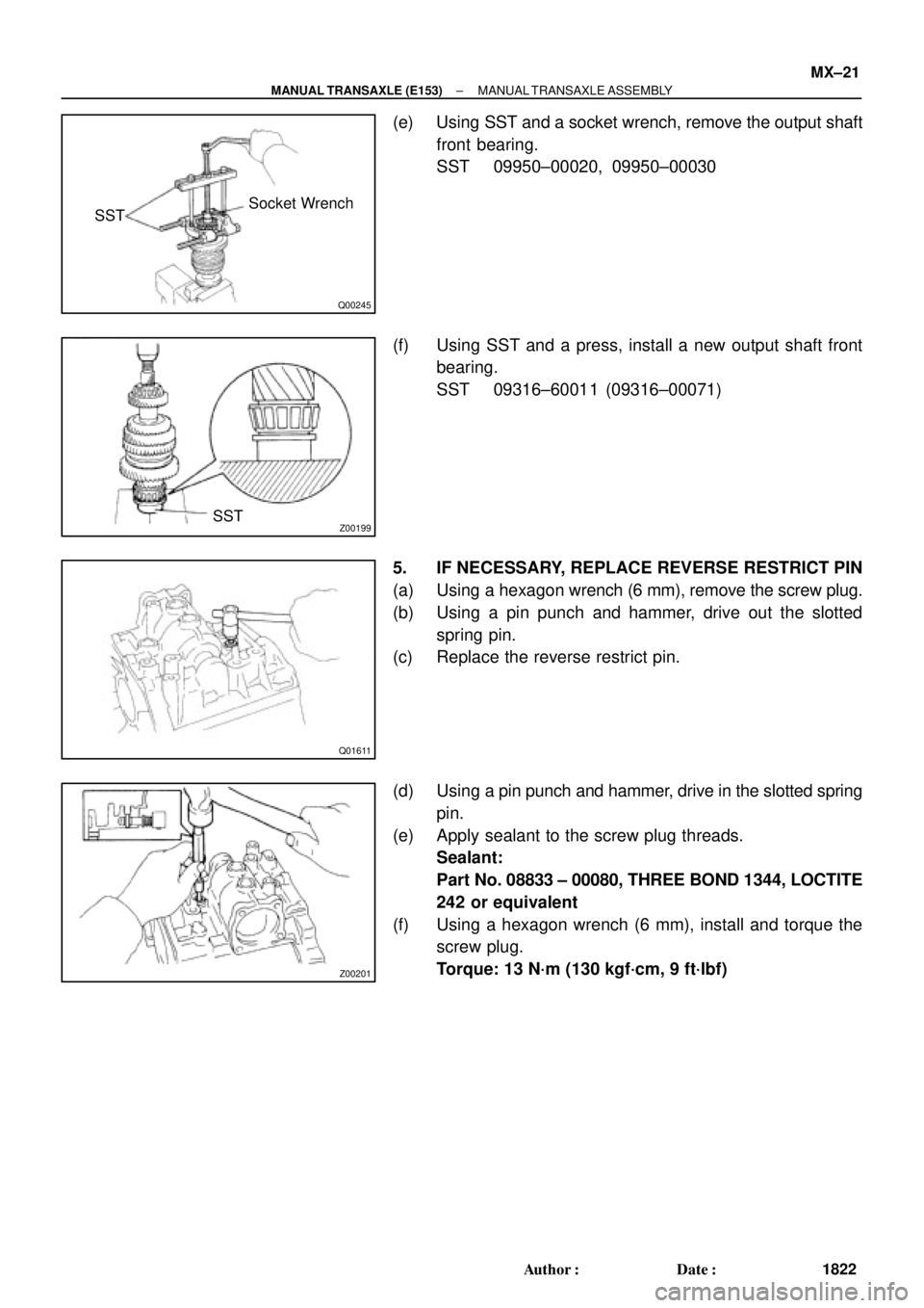
(e) Using SST and a socket wrench, remove the output shaft
front bearing.
SST 09950±00020, 09950±00030
(f) Using SST and a press, install a new output shaft front
bearing.
SST 09316±60011 (09316±00071)
5. IF NECESSARY, REPLACE REVERSE RESTRICT PIN
(a) Using a hexagon wrench (6 mm), remove the screw plug.
(b) Using a pin punch and hammer, drive out the slotted
spring pin.
(c) Replace the reverse restrict pin.
(d) Using a pin punch and hammer, drive in the slotted spring
pin.
(e) Apply sealant to the screw plug threads.
Sealant:
Part No. 08833 ± 00080, THREE BOND 1344, LOCTITE
242 or equivalent
(f) Using a hexagon wrench (6 mm), install and torque the
screw plug.
Torque: 13 N´m (130 kgf´cm, 9 ft´lbf)
Page 2955 of 4592
MANUAL TRANSAXLE ASSEMBLY
1823 Author�: Date�:
REASSEMBLY
Reassembly is in the reverse order of disassembly.
HINT:
�Before reassembly, select a shim by adjus")
MX055±01
MX±22
± MANUAL TRANSAXLE (E153)MANUAL TRANSAXLE ASSEMBLY
1823 Author�: Date�:
REASSEMBLY
Reassembly is in the reverse order of disassembly.
HINT:
�Before reassembly, select a shim by adjusting output
shaft preload.
�Coat all of the sliding and rotating surfaces with gear oil
before reassembly.
ADJUST OUTPUT SHAFT PRELOAD
(a) Install the output shaft assembly to the transaxle case.
(b) Install the transmission case to the transaxle case.
HINT:
If necessary, tap on the case with a plastic hammer.
(c) Install and torque the 17 bolts.
Torque: 29 N´m (300 kgf´cm, 22 ft´lbf)
(d) Install the output shaft rear taper roller bearing outer race.
(e) Install the adjusting shim.
HINT:
When reusing the output shaft bearing, first install a shim of the
same thickness as before. If installing a new taper roller bear-
ing, first select and install a shim of lesser thickness than be-
fore.
(f) Install the rear bearing retainer.
(g) Using a torx wrench (T45), install and torque the 7 torx
screws.
Torque: 42 N´m (430 kgf´cm, 31 ft´lbf)
(h) Install a new lock nut to the output shaft.
(i) Turn the output shaft right and left 2 or 3 times to allow the
bearing to settle.
Page 2956 of 4592
MANUAL TRANSAXLE ASSEMBLY
MX±23
1824 Author�: Date�:
(j) Using a torque wrench, measure the preload.
Preload (at starting):
New bearing
0.8 ± 1.6 N´m (8 ± 16 kgf´")
Z12593
± MANUAL TRANSAXLE (E153)MANUAL TRANSAXLE ASSEMBLY
MX±23
1824 Author�: Date�:
(j) Using a torque wrench, measure the preload.
Preload (at starting):
New bearing
0.8 ± 1.6 N´m (8 ± 16 kgf´cm, 6.9 ± 13.9 in.´lbf)
Reused bearing
0.5 ± 1.0 N´m (5 ± 10 kgf´cm, 4.3 ± 8.7 in.´lbf)
If the preload is not within the specification, select an appropri-
ate adjusting shim.
The preload will change approx. 0.4 ± 0.5 N´m (4 ± 5 kgf´cm, 3.5
± 4.3 in.´lbf) for every 0.05 mm change in adjusting shim thick-
ness.
MarkThickness mm (in.)MarkThickness mm (in.)
01.30 (0.0512)D1.95 (0.0768)
11.35 (0.0531)E2.00 (0.0787)
21.40 (0.0551)F2.05 (0.0807)
31.45 (0.0571)G2.10 (0.0827)
41.50 (0.0591)H2.15 (0.0846)
51.55 (0.0610)J2.20 (0.0866)
61.60 (0.0630)K2.25 (0.0886)
71.65 (0.0650)L2.30 (0.0906)
81.70 (0.0669)M2.35 (0.0925)
91.75 (0.0689)N2.40 (0.0945)
A1.80 (0.0709)P2.45 (0.0965)
B1.85 (0.0728)Q2.50 (0.0984)
C1.90 (0.0748)±±
(k) Remove the lock nut.
(l) Remove these parts. Removal is in the reverse order of
installation.
�Rear bearing retainer
�Shim
�Transmission case
�Output shaft assembly
�Output shaft rear bearing outer race
Page 2972 of 4592
MX05E±01
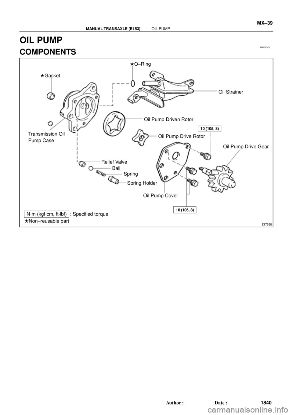
Z17558
�Gasket�O±Ring
Transmission Oil
Pump Case
Relief Valve
Ball
Spring
Spring Holder
Oil Pump CoverOil Pump Drive Gear Oil Strainer
Oil Pump Driven Rotor
Oil Pump Drive Rotor
10 (105, 8)
10 (105, 8)N´m (kgf´cm, ft´lbf) : Specified torque
�Non±reusable part
± MANUAL TRANSAXLE (E153)OIL PUMP
MX±39
1840 Author�: Date�:
OIL PUMP
COMPONENTS
Page 2978 of 4592
Z00292
SST
Z00293
SST
Z19038
FIPGF
± MANUAL TRANSAXLE (E153)DIFFERENTIAL CASE
MX±45
1846 Author�: Date�:
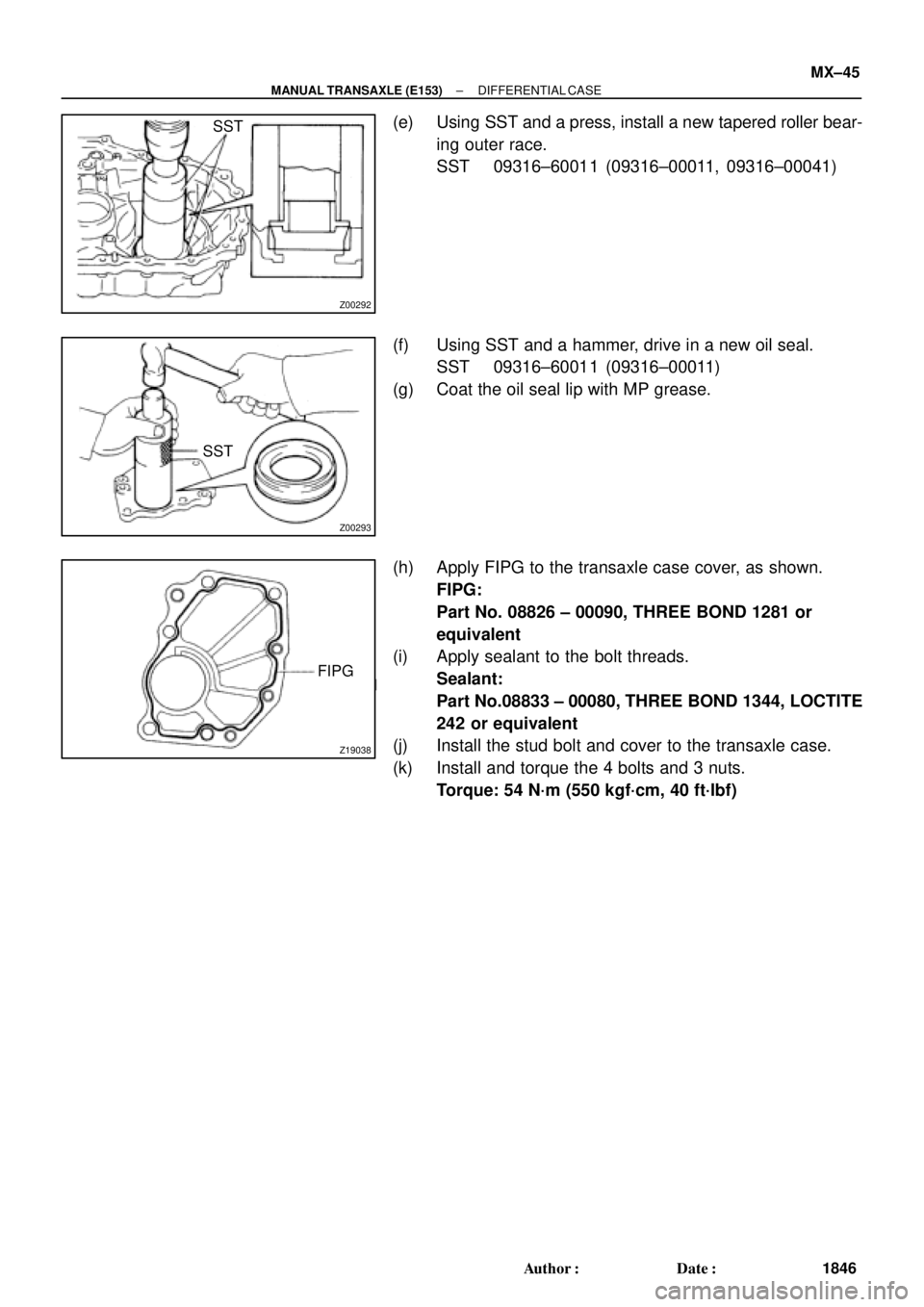
(e) Using SST and a press, install a new tapered roller bear-
ing outer race.
SST 09316±60011 (09316±00011, 09316±00041)
(f) Using SST and a hammer, drive in a new oil seal.
SST 09316±60011 (09316±00011)
(g) Coat the oil seal lip with MP grease.
(h) Apply FIPG to the transaxle case cover, as shown.
FIPG:
Part No. 08826 ± 00090, THREE BOND 1281 or
equivalent
(i) Apply sealant to the bolt threads.
Sealant:
Part No.08833 ± 00080, THREE BOND 1344, LOCTITE
242 or equivalent
(j) Install the stud bolt and cover to the transaxle case.
(k) Install and torque the 4 bolts and 3 nuts.
Torque: 54 N´m (550 kgf´cm, 40 ft´lbf)
Page 2980 of 4592
DIFFERENTIAL CASE
MX±47
1848 Author�: Date�:
(h) Align the matchmarks on the differential cases.
(i) Using a plastic")
Z00299
Matchmarks
Z00303
Driven Gear
Side
Q06410
SST
SST
± MANUAL TRANSAXLE (E153)DIFFERENTIAL CASE
MX±47
1848 Author�: Date�:
(h) Align the matchmarks on the differential cases.
(i) Using a plastic hammer, carefully tap the differential case
to install it.
(j) Using a torx wrench (T50), install and torque the 16 torx
screws.
Torque: 63 N´m (640 kgf´cm, 46 ft´lbf)
2. INSTALL RING GEAR
(a) Clean the contact surface of the differential case and the
threads of the ring gear and differential case.
(b) Heat the ring gear in boiling water.
(c) Carefully remove the ring gear from the water.
(d) After the moisture on the ring gear has completely evapo-
rated, quickly install the ring gear to the differential case.
HINT:
Align the matchmarks on the differential left case.
(e) Temporarily install the 16 bolts.
NOTICE:
The ring gear set bolts should not be tightened until the
ring gear has cooled sufficiently.
(f) After the ring gear has cooled sufficiently, torque the ring
gear set bolts.
Torque: 124 N´m (1,260 kgf´cm, 91 ft´lbf)
3. INSTALL TAPERED ROLLER BEARING
Using SST and a press, install new left and right bearings onto
the differential case.
SST 09316±20011, 09316±60011 (09316±00011)
HINT:
Press the bearing on the ring side first.
4. ADJUST OUTPUT SHAFT ASSEMBLY PRELOAD
(See pages MX±22)
5. INSTALL DIFFERENTIAL CASE ASSEMBLY TO
TRANSAXLE CASE
6. INSTALL OUTPUT SHAFT ASSEMBLY
Lift up the differential case and install the output shaft assem-
bly.
7. INSTALL TRANSMISSION CASE
(a) Install the transmission case.
HINT:
If necessary, tap on the case with a plastic hammer.
(b) Install and torque the 17 bolts.
Torque: 29 N´m (300 kgf´cm 22 ft´lbf)