Page 1132 of 4592
CL03G±01
Q10092
Starter
21 (210, 15)
39 (400, 29)
13 (130, 9)13 (130, 9)
Clutch Accumulator Bracket
N´m (kgf´cm, ft´lbf)
: Specified torqueCruise Control
Actuator
Battery w/ Cruise Control System :
27 (270, 20)
15 (155, 11)
CL±14
± CLUTCHCLUTCH ACCUMULATOR (1MZ±FE)
1793 Author�: Date�:
CLUTCH ACCUMULATOR (1MZ±FE)
COMPONENTS
Page 1133 of 4592
CL03H±01
Q10074
Q10078
Q10076
SST
± CLUTCHCLUTCH ACCUMULATOR (1MZ±FE)
CL±15
1794 Author�: Date�:
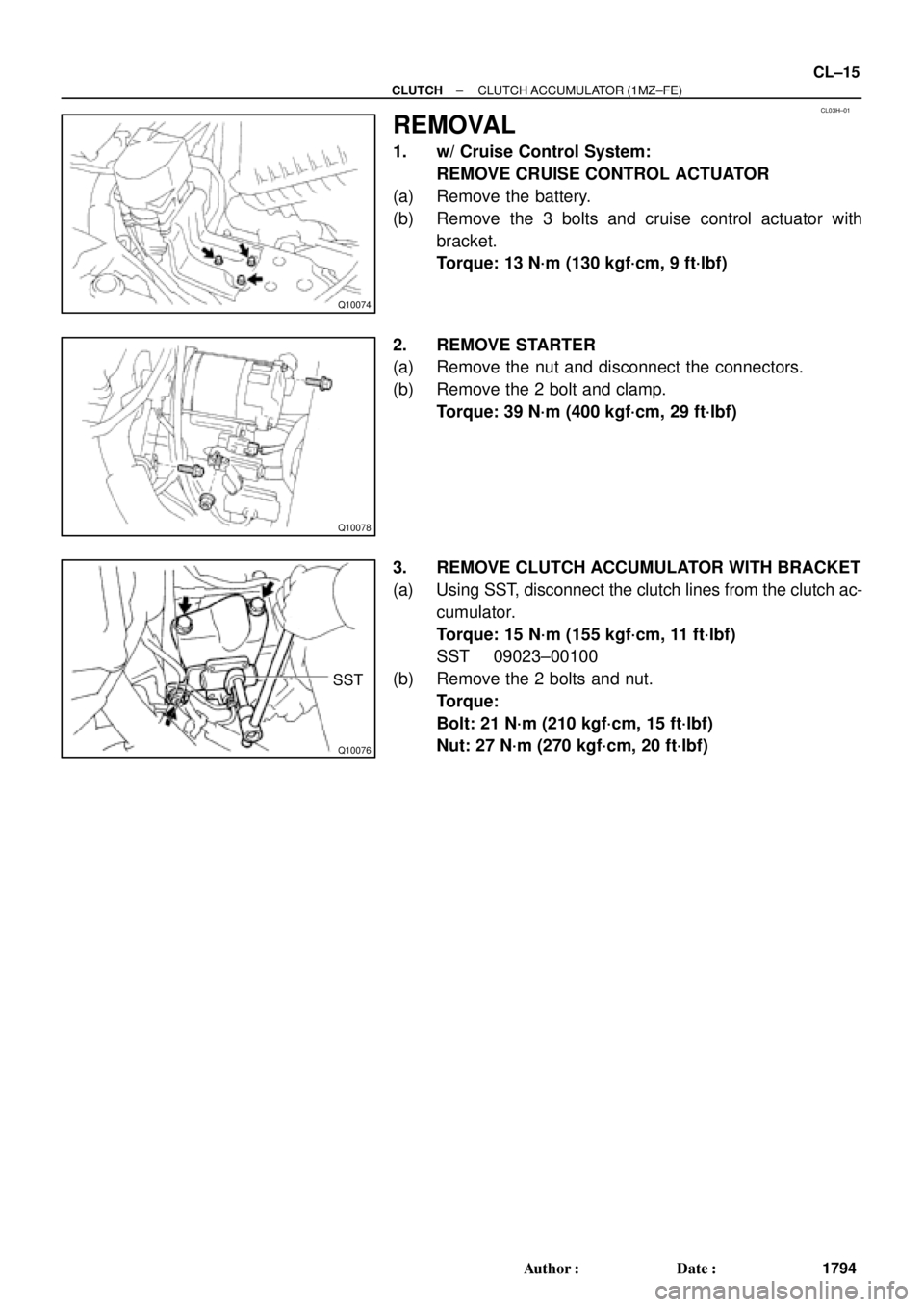
REMOVAL
1. w/ Cruise Control System:
REMOVE CRUISE CONTROL ACTUATOR
(a) Remove the battery.
(b) Remove the 3 bolts and cruise control actuator with
bracket.
Torque: 13 N´m (130 kgf´cm, 9 ft´lbf)
2. REMOVE STARTER
(a) Remove the nut and disconnect the connectors.
(b) Remove the 2 bolt and clamp.
Torque: 39 N´m (400 kgf´cm, 29 ft´lbf)
3. REMOVE CLUTCH ACCUMULATOR WITH BRACKET
(a) Using SST, disconnect the clutch lines from the clutch ac-
cumulator.
Torque: 15 N´m (155 kgf´cm, 11 ft´lbf)
SST 09023±00100
(b) Remove the 2 bolts and nut.
Torque:
Bolt: 21 N´m (210 kgf´cm, 15 ft´lbf)
Nut: 27 N´m (270 kgf´cm, 20 ft´lbf)
Page 1135 of 4592
CL03J±01
Q10017
Flywheel
Clutch Disc
19 (195, 14)
47 (480, 35)
Clutch Coverx 6
Release Bearing and Hub
Release Fork5S±FE :
Release Fork
39 (400, 29)
5S±FE :
Clutch Disc
N´m (kgf´cm, ft´lbf) : Specified torqueBoot
± CLUTCHCLUTCH UNIT
CL±17
1796 Author�: Date�:
CLUTCH UNIT
COMPONENTS
Page 1139 of 4592
CL03M±02
Q10089
1MZ±FE:
5S±FE:SST
Flywheel
Side
SST
Q10084
SST
1
Matchmarks
4
2
6
35
Q10072
SST
± CLUTCHCLUTCH UNIT
CL±21
1800 Author�: Date�:
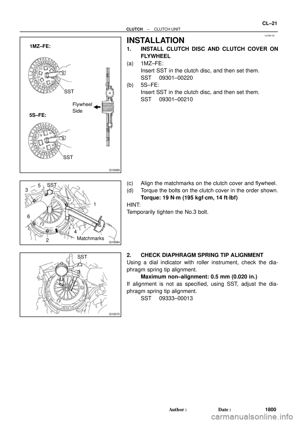
INSTALLATION
1. INSTALL CLUTCH DISC AND CLUTCH COVER ON
FLYWHEEL
(a) 1MZ±FE:
Insert SST in the clutch disc, and then set them.
SST 09301±00220
(b) 5S±FE:
Insert SST in the clutch disc, and then set them.
SST 09301±00210
(c) Align the matchmarks on the clutch cover and flywheel.
(d) Torque the bolts on the clutch cover in the order shown.
Torque: 19 N´m (195 kgf´cm, 14 ft´lbf)
HINT:
Temporarily tighten the No.3 bolt.
2. CHECK DIAPHRAGM SPRING TIP ALIGNMENT
Using a dial indicator with roller instrument, check the dia-
phragm spring tip alignment.
Maximum non±alignment: 0.5 mm (0.020 in.)
If alignment is not as specified, using SST, adjust the dia-
phragm spring tip alignment.
SST 09333±00013
Page 1142 of 4592
COOLANT
1576 Author�: Date�:
REPLACEMENT
1. DRAIN ENGINE COOLANT
(a) Remove the radiator cap.
CAUTION:
To avoid the dang")
CO067±03
Z18990
Radiator Drain Plug
Engine Drain Plug CO±2
± COOLING (5S±FE)COOLANT
1576 Author�: Date�:
REPLACEMENT
1. DRAIN ENGINE COOLANT
(a) Remove the radiator cap.
CAUTION:
To avoid the danger of being burned, do not remove the ra-
diator cap while the engine and radiator are still hot, as fluid
and steam can be blown out under pressure.
(b) Loosen the radiator drain plug (on the right side of the ra-
diator lower tank) and engine drain plug (on the left rear
of the cylinder block), and drain the coolant.
(c) Close the drain plugs.
Torque: 25 N´m (250 kgf´cm, 18 ft´lbf) for engine
2. FILL ENGINE COOLANT
(a) Slowly fill the system with coolant.
�Use of improper coolants may damage engine cool-
ing system.
�Use ºToyota Long Life Coolantº or equivalent and
mix it with plan water according to the manufactur-
er's directions.
�Using of coolant which includes more than 50 %
(freezing protection down to ±35°C (±31°F) or 60 %
(freezing protection down to ±50°C (±58°F)) of eth-
ylene±glycol is recommended but not more than 70
%.
NOTICE:
�Do not use an alcohol type coolant or plain water
alone.
�The coolant should be mixed with plain water (prefer-
ably demineralized water or distilled water).
Capacity:
w/ Oil cooler6.9 litters (7.3 US qts, 6.1 lmp. qts)
w/o Oil cooler6.2 litters (6.5 US qts, 5.4 lmp. qts)
(b) Install the radiator cap.
(c) Start the engine, and bleed the cooling system.
(d) Refill the radiator reservoir with coolant until it reaches the
ºFULLº line.
3. CHECK FOR COOLANT LEAKS
Page 1143 of 4592
CO068±03
S05543
Engine Moving Control Rod
No.2 RH Engine Mounting Bracket
Generator Drive Belt
w/ Oil Cooler
A/C Compressor
Connector
A/C Compressor
Cylinder Block Insulator
N´m (kgf´cm, ft´lbf)RH Front Fender Apron SealPS Pump Drive BeltGround Strap Connector
: Specified torque
64 (650, 47)
64 (650, 47)
52 (530, 38)
± COOLING (5S±FE)WATER PUMP
CO±3
1577 Author�: Date�:
WATER PUMP
COMPONENTS
Page 1144 of 4592
S05939
No.2 Timing Belt
Cover
No.1 Timing Belt
Cover
Crankshaft
Pulley
No.2 Idler Pulley
Generator Drive Belt
Adjusting Bar
Wire Clamp
Crankshaft Position Sensor
Connector* Gasket
No.1 Idler Pulley
Tension Spring
� O±Ring
Water PumpWater PumpTiming Belt
Timing Belt Guide
Lower
Radiator
Hose Water Pump and
Water Pump Cover
Assembly High±Tension Cord Generator Wire
� Gasket Wire Clamp
Wire Clamp
Wire ClampWire Clamp Wire
Clamp
* GasketGenerator Connector
Generator
Spark Plug
� O±Ring
� Gasket
N´m (kgf´cm, ft´lbf): Specified torque
� Non±reusable part
108 (1,100, 80)18 (180,13)
42 (425,31)
42 (425,31)
* Replace only if damagedCover CO±4
± COOLING (5S±FE)WATER PUMP
1578 Author�: Date�:
Page 1148 of 4592
WATER PUMP
1582 Author�: Date�:
INSTALLATION
1. INSTALL WATER PUMP TO WATER PUMP COVER
Install a new gasket and the")
CO06B±03
N00918
S06015
Connect
Z19283
1
3
2
S05924
S05599
CO±8
± COOLING (5S±FE)WATER PUMP
1582 Author�: Date�:
INSTALLATION
1. INSTALL WATER PUMP TO WATER PUMP COVER
Install a new gasket and the water pump with the 3 bolts.
Torque: 8.8 N´m (90 kgf´cm, 78 in.´lbf)
2. INSTALL WATER PUMP AND WATER PUMP COVER
ASSEMBLY
(a) Install new O±ring and gasket to water pump cover.
(b) Install a new O±ring to the water bypass pipe.
(c) Apply soapy water to the O±ring on the water bypass
pipe.
(d) Connect the water pump cover to the water bypass pipe.
Do not install the nuts yet.
(e) Install the water pump with the 3 bolts. Tighten the bolts
in the sequence shown.
Torque: 8.8 N´m (90 kgf´cm, 78 in.´lbf)
(f) Install the 2 nuts holding the water pump cover to the wa-
ter bypass pipe.
Torque: 9.3 N´m (95 kgf´cm, 82 in.´lbf)
3. INSTALL GENERATOR DRIVE BELT ADJUSTING BAR
(a) Install the adjusting bar with the bolt.
Torque: 22 N´m (224 kgf´cm, 16 ft´lbf)
(b) Install the engine wire clamp to the adjusting bar.
(c) Install the crankshaft position sensor connector to the
bracket on the adjusting bar.
4. w/ Oil Cooler:
INSTALL A/C COMPRESSOR (See page EM±75)
5. INSTALL NO.2 IDLER PULLEY (See page EM±23)

39 (400, 29)
13 (130, 9)13 (130, 9)
Clutch Accumulator Bracket
N´m (kgf´cm, ft´lbf)
: Specified torqueCruise Control
Actuator
Battery w/ Cruise Control System")

47 (480, 35)
Clutch Coverx 6
Release Bearing and Hub
Release Fork5S±FE :
Release Fork
39 (400, 29)
5S±FE :
Clutch Disc
N´m (kgf´cm, ft´lbf) : Sp")
RH")
