Page 1072 of 4592
BR0BJ±02
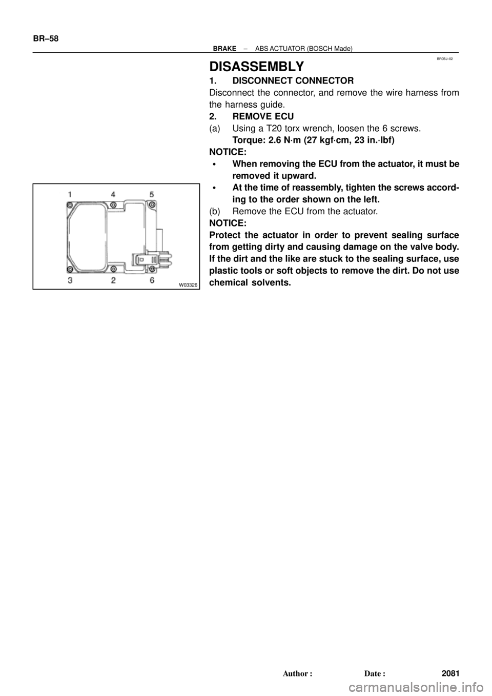
W03326
BR±58
± BRAKEABS ACTUATOR (BOSCH Made)
2081 Author�: Date�:
DISASSEMBLY
1. DISCONNECT CONNECTOR
Disconnect the connector, and remove the wire harness from
the harness guide.
2. REMOVE ECU
(a) Using a T20 torx wrench, loosen the 6 screws.
Torque: 2.6 N´m (27 kgf´cm, 23 in.´lbf)
NOTICE:
�When removing the ECU from the actuator, it must be
removed it upward.
�At the time of reassembly, tighten the screws accord-
ing to the order shown on the left.
(b) Remove the ECU from the actuator.
NOTICE:
Protect the actuator in order to prevent sealing surface
from getting dirty and causing damage on the valve body.
If the dirt and the like are stuck to the sealing surface, use
plastic tools or soft objects to remove the dirt. Do not use
chemical solvents.
Page 1078 of 4592
BR077±04
W03272
Cushion
HolderABS & TRAC
Actuator
A/C Tube Clamp
Bracket
Actuator Bracket
15 (155, 11)
5.4 (55, 48 in.´lbf)
19 (195, 14)
N´m (kgf´cm, ft´lbf) : Specified torque
19 (195, 14)
Cushion
20 (200, 14)
BR±64
± BRAKEABS & TRAC ACTUATOR
2087 Author�: Date�:
COMPONENTS
Page 1079 of 4592
BR078±03
W03245
SST
± BRAKEABS & TRAC ACTUATOR
BR±65
2088 Author�: Date�:
REMOVAL
1. REMOVE RIGHT FRONT FENDER LINER
2. REMOVE A/C TUBE CLAMP BRACKET BOLT
3. DISCONNECT BRAKE LINES
Using SST, disconnect the 6 brake lines from the ABS & TRAC
actuator.
SST 09751±36011
Torque:
10 mm nut 15 N´m (155 kgf´cm, 11 ft´lbf)
12 mm nut 20 N´m (200 kgf´cm, 14 ft´lbf)
4. REMOVE ABS & TRAC ACTUATOR ASSEMBLY
(a) Disconnect the 2 connectors.
(b) Remove the 2 blots, 2 nuts and ABS & TRAC actuator as-
sembly.
Torque: 19 N´m (195 kgf´cm, 14 ft´lbf)
5. REMOVE ABS & TRAC ACTUATOR
(a) Remove the 2 nuts and ABS & TRAC actuator from actua-
tor bracket.
Torque: 5.4 N´m (55 kgf´cm, 48 in.´lbf)
(b) Remove the 2 holders and 3 cushions from the ABS &
TRAC actuator.
Page 1081 of 4592
BR0BQ±03
W03273
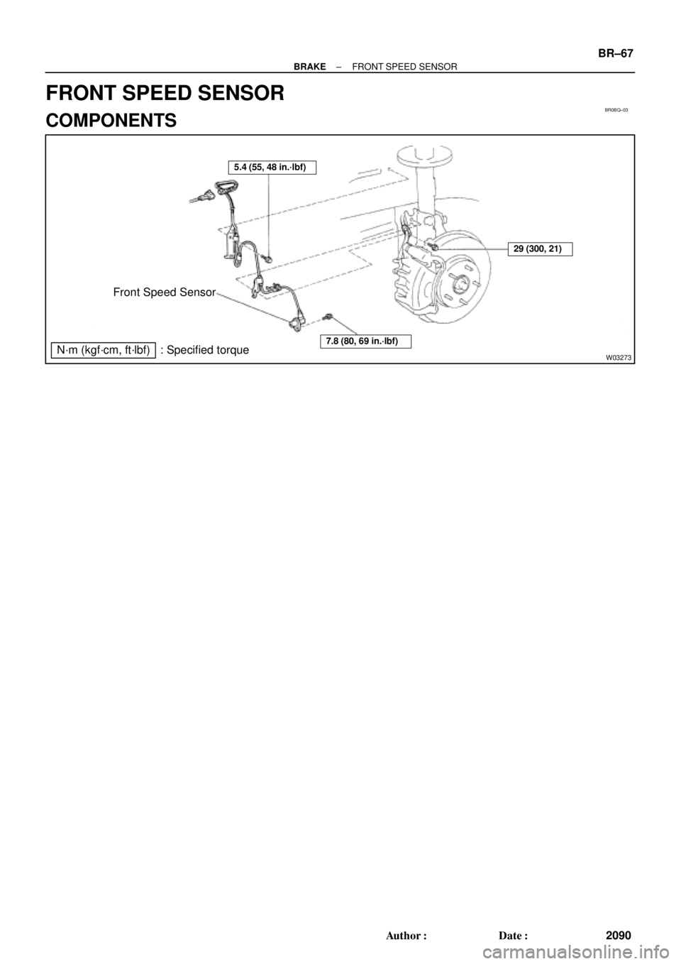
Front Speed Sensor
N´m (kgf´cm, ft´lbf) : Specified torque
5.4 (55, 48 in.´lbf)
7.8 (80, 69 in.´lbf)
29 (300, 21)
± BRAKEFRONT SPEED SENSOR
BR±67
2090 Author�: Date�:
FRONT SPEED SENSOR
COMPONENTS
Page 1082 of 4592
BR0BR±03
R00327
W04507
BR±68
± BRAKEFRONT SPEED SENSOR
2091 Author�: Date�:
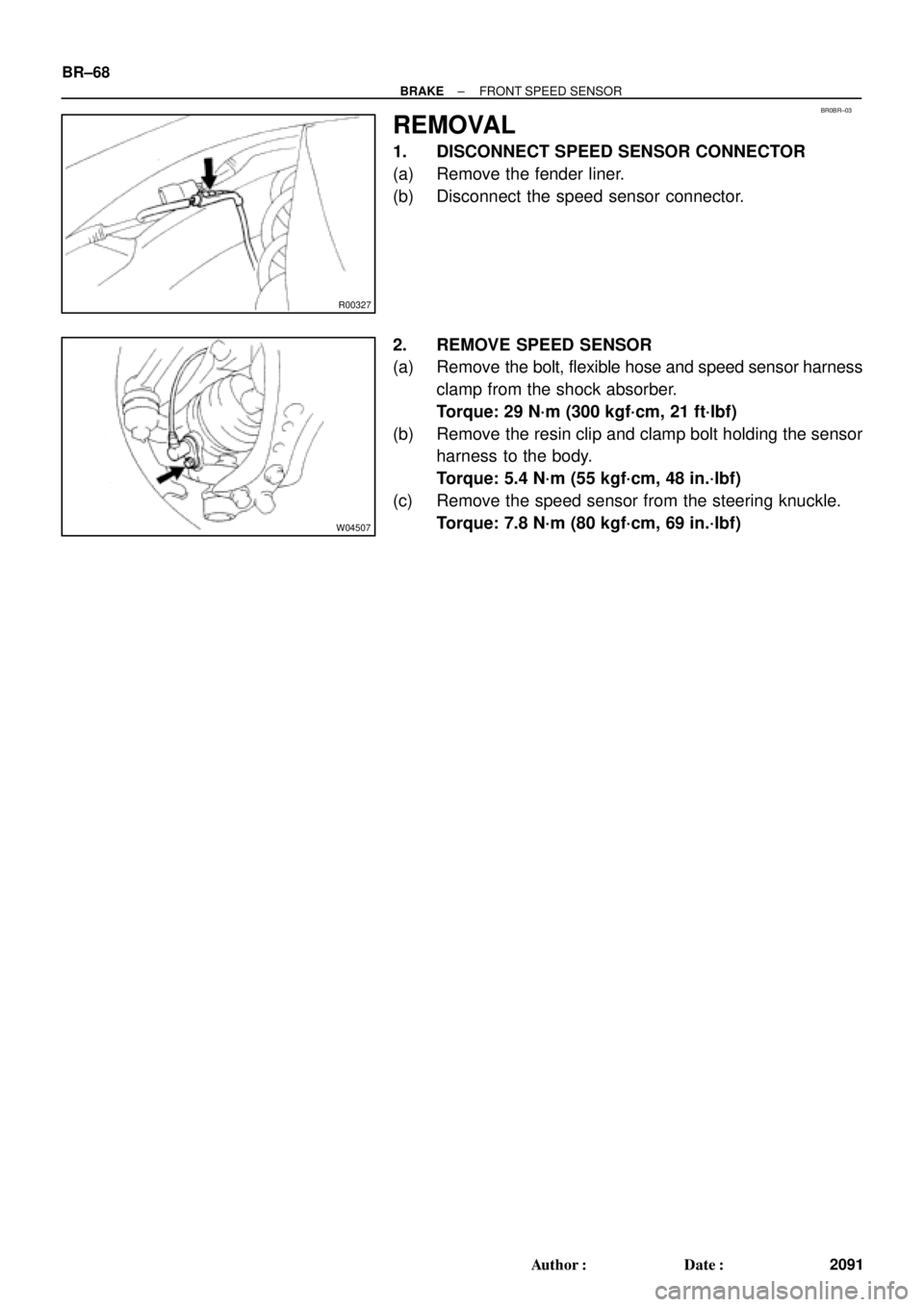
REMOVAL
1. DISCONNECT SPEED SENSOR CONNECTOR
(a) Remove the fender liner.
(b) Disconnect the speed sensor connector.
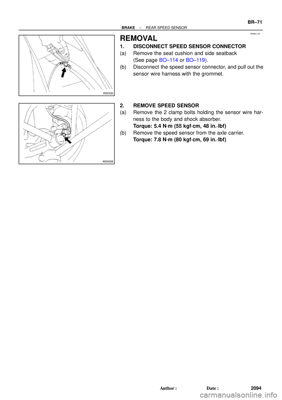
2. REMOVE SPEED SENSOR
(a) Remove the bolt, flexible hose and speed sensor harness
clamp from the shock absorber.
Torque: 29 N´m (300 kgf´cm, 21 ft´lbf)
(b) Remove the resin clip and clamp bolt holding the sensor
harness to the body.
Torque: 5.4 N´m (55 kgf´cm, 48 in.´lbf)
(c) Remove the speed sensor from the steering knuckle.
Torque: 7.8 N´m (80 kgf´cm, 69 in.´lbf)
Page 1084 of 4592
BR0BT±03
W03274
Rear Speed Sensor
N´m (kgf´cm, ft´lbf): Specified torque
5.4 (55, 48 in.´lbf)
7.8 (80, 69 in.´lbf)
5.4 (55, 48 in.´lbf)
BR±70
± BRAKEREAR SPEED SENSOR
2093 Author�: Date�:
REAR SPEED SENSOR
COMPONENTS
Page 1085 of 4592
BR0BU±03
R00330
W04508
± BRAKEREAR SPEED SENSOR
BR±71
2094 Author�: Date�:
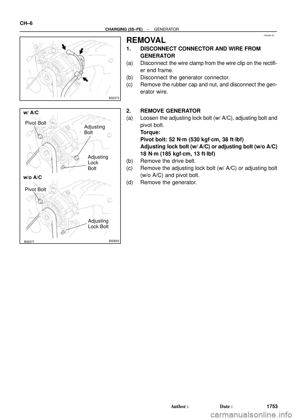
REMOVAL
1. DISCONNECT SPEED SENSOR CONNECTOR
(a) Remove the seat cushion and side seatback
(See page BO±114 or BO±119).
(b) Disconnect the speed sensor connector, and pull out the
sensor wire harness with the grommet.
2. REMOVE SPEED SENSOR
(a) Remove the 2 clamp bolts holding the sensor wire har-
ness to the body and shock absorber.
Torque: 5.4 N´m (55 kgf´cm, 48 in.´lbf)
(b) Remove the speed sensor from the axle carrier.
Torque: 7.8 N´m (80 kgf´cm, 69 in.´lbf)
Page 1092 of 4592
CH02W±03
B02375
B02376B02377B02693
w/o A/C
w/ A/C
Pivot BoltAdjusting
Bolt
Adjusting
Lock
Bolt
Pivot Bolt
Adjusting
Lock Bolt
CH±6
± CHARGING (5S±FE)GENERATOR
1753 Author�: Date�:
REMOVAL
1. DISCONNECT CONNECTOR AND WIRE FROM
GENERATOR
(a) Disconnect the wire clamp from the wire clip on the rectifi-
er end frame.
(b) Disconnect the generator connector.
(c) Remove the rubber cap and nut, and disconnect the gen-
erator wire.
2. REMOVE GENERATOR
(a) Loosen the adjusting lock bolt (w/ A/C), adjusting bolt and
pivot bolt.
Torque:
Pivot bolt: 52 N´m (530 kgf´cm, 38 ft´lbf)
Adjusting lock bolt (w/ A/C) or adjusting bolt (w/o A/C)
18 N´m (185 kgf´cm, 13 ft´lbf)
(b) Remove the drive belt.
(c) Remove the adjusting lock bolt (w/ A/C) or adjusting bolt
(w/o A/C) and pivot bolt.
(d) Remove the generator.

5.4 (55, 48 in.´lbf)
19 (195, 14)
N´m (kgf´cm, ft´lbf) : Specified torque
19 (195, 14)
Cushi")