Page 1026 of 4592
 Remove the set screw and pull out the reservoir.
Torq")
BR0AG±02
R11406
Soft Jows
R11407
Soft Jows
R12236
A BR±12
± BRAKEBRAKE MASTER CYLINDER
2035 Author�: Date�:
DISASSEMBLY
1. REMOVE RESERVOIR
(a) Remove the set screw and pull out the reservoir.
Torque: 1.7 N´m (18 kgf´cm, 16 in.´lbf)
(b) Remove the cap and strainer from the reservoir.
2. REMOVE 2 GROMMETS
3. Except w/ TRAC:
PLACE CYLINDER IN VISE
4. w/o TRAC:
REMOVE PISTON STOPPER BOLT
Using a screwdriver, push the pistons in all the way and remove
the piston stopper bolt and gasket.
HINT:
Tape the screwdriver tip before use.
Torque: 10 N´m (100 kgf´cm, 7 ft´lbf)
5. w/o TRAC:
REMOVE 2 PISTONS AND SPRINGS
(a) Push in the piston with a screwdriver and remove the
snap ring with snap ring pliers.
HINT:
Tape the screwdriver tip before use.
(b) Remove the No. 1 piston and spring by hand, pulling
straight out, not at an angle.
NOTICE:
�If pulled out and installed at an angle, there is a possi-
bility that the cylinder bore could be damaged.
�At the time of reassembly, please refer to the follow-
ing item.
Be careful not to damage the rubber lips on the pis-
tons.
(c) Place a rag and 2 wooden blocks on the work table, and
lightly tap the cylinder flange against the block edges until
the No. 2 piston drops out of the cylinder.
HINT:
Make sure that the distance (A) from the rag to the top of the
blocks is at least 100 mm (3.94 in.).
Page 1032 of 4592
BR0AL±03
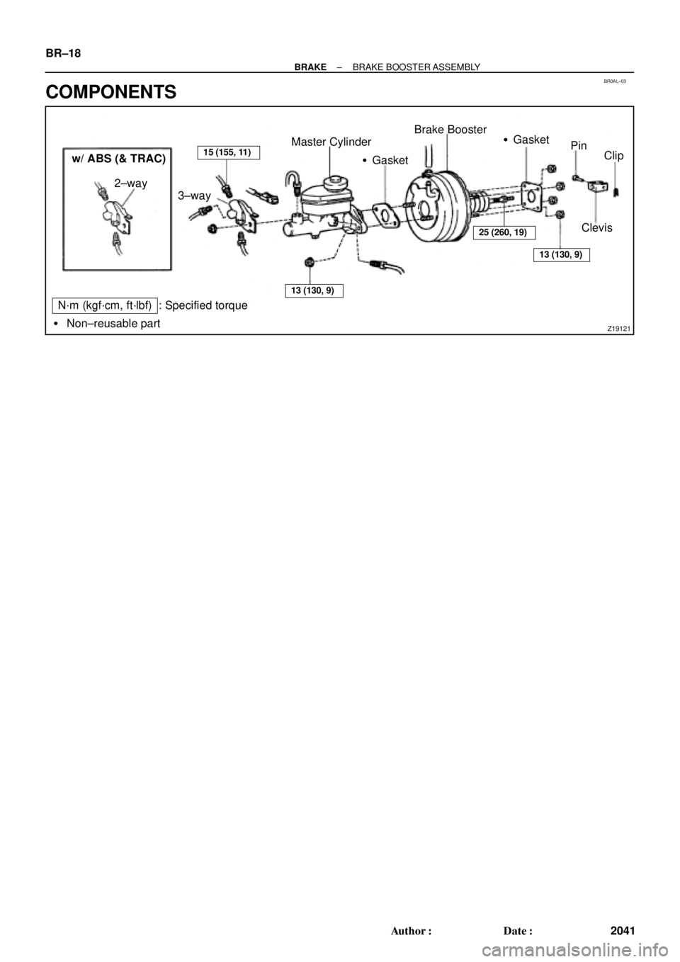
Z19121
Master Cylinder
�GasketBrake Booster
�Gasket
Pin
Clip
Clevis 2±way
� Non±reusable part
N´m (kgf´cm, ft´lbf) : Specified torquew/ ABS (& TRAC)
3±way
15 (155, 11)
13 (130, 9)
25 (260, 19)
13 (130, 9)
BR±18
± BRAKEBRAKE BOOSTER ASSEMBLY
2041 Author�: Date�:
COMPONENTS
Page 1034 of 4592
 Install the booster and a new gasket.
(b) Install the clevis")
BR0AN±03
F03521
SST
Gasket
R11347
SST BR±20
± BRAKEBRAKE BOOSTER ASSEMBLY
2043 Author�: Date�:
INSTALLATION
1. INSTALL BRAKE BOOSTER
(a) Install the booster and a new gasket.
(b) Install the clevis to the operating rod.
(c) Install and torque the booster installation nuts.
Torque: 13 N´m (130 kgf´cm, 9 ft´lbf)
(d) Install the clevis, and torque the lock nut.
Torque: 25 N´m (260 kgf´cm, 19 ft´lbf)
(e) Install the clevis pin into the clevis and brake pedal, and
install the clip to the clevis pin.
(f) Install the pedal return spring.
2. ADJUST LENGTH OF BOOSTER PUSH ROD
(a) Install a new gasket on the master cylinder.
(b) Set the SST on the gasket, and lower the pin until its tip
slightly touches the piston.
SST 09737±00010
(c) Turn the SST upside down, and set it on the booster.
SST 09737±00010
(d) Measure the clearance between the booster push rod
and pin head (SST).
Clearance: 0 mm (0 in.)
(e) Adjust the booster push rod length until the push rod light-
ly touches the pin head.
3. INSTALL CHARCOAL CANISTER TO ORIGINAL POSI-
TION
4. INSTALL MASTER CYLINDER (See page BR±16)
5. INSTALL AIR CLEANER COVER WITH AIR CLEANER
HOSE
6. CONNECT VACUUM HOSE TO BRAKE BOOSTER
7. FILL BRAKE RESERVOIR WITH BRAKE FLUID AND
BLEED BRAKE SYSTEM (See page BR±4)
8. CHECK FOR FLUID LEAKAGE
9. CHECK AND ADJUST BRAKE PEDAL
(See page BR±5)
10. DO OPERATIONAL CHECK (See page BR±17)
Page 1035 of 4592
BR0AO±03
F06983F07224
F07225
Anti±squeal Shim
Inner Anti±squeal Shim
Anti±squeal Spring
Pad Support Plate
Inner PadOuter Pad
1MZ±FE engine: 5S±FE engine:
Anti±squeal Shim
Inner Anti±squeal Shim
Pad Wear Indicator Plate
Outer Pad
Pad Support Plate
Inner Pad
Disc brake grease
N´m (kgf´cm, ft´lbf): Specified torque
34 (350, 25)
34 (350, 25)
± BRAKEFRONT BRAKE PAD
BR±21
2044 Author�: Date�:
FRONT BRAKE PAD
COMPONENTS
Page 1037 of 4592
 1MZ±FE engine:
Install a pad wear indicator plate on the inner pad.
(b) Apply disc brake grease to both sides of the inner anti±")
R00595
R02981
± BRAKEFRONT BRAKE PAD
BR±23
2046 Author�: Date�:
(a) 1MZ±FE engine:
Install a pad wear indicator plate on the inner pad.
(b) Apply disc brake grease to both sides of the inner anti±
squeal shims (See page BR±21).
(c) Install the 2 anti±squeal shims on each pad.
(d) Install inner pad with the pad wear indicator plate facing
upward.
(e) Install inner pad.
(f) Install outer pad.
NOTICE:
There should be no oil or grease adhering to the friction
surfaces of the pads or the disc.
(g) 5S±FE engine:
Install the 2 anti±squeal springs.
13. INSTALL CALIPER
(a) Draw out a small amount of brake fluid from the reservoir.
(b) Press in the piston with a hammer handle or similar imple-
ment.
HINT:
If the piston is difficult to push in, loosen the bleeder plug and
push in the piston while letting some brake fluid escape.
(c) Install the caliper.
(d) 5S±FE engine:
Hold the sliding pin and torque the installation bolt.
(e) 1MZ±FE engine:
Install the installation bolt.
Torque: 34 N´m (350 kgf´cm, 25 ft´lbf)
(f) Install the flexible hose and bolt to the bracket.
Torque: 29 N´m (300 kgf´cm, 21 ft´lbf)
14. INSTALL FRONT WHEEL
Torque: 103 N´m (1,050 kgf´cm, 76 ft´lbf)
15. DEPRESS BRAKE PEDAL SEVERAL TIMES
16. CHECK THAT FLUID LEVEL IS AT MAX LINE
Page 1038 of 4592
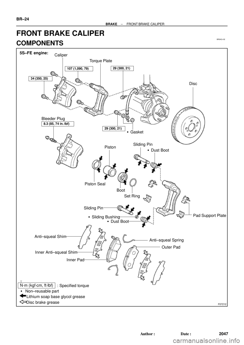
BR0AQ±02
F07212
Caliper
Torque Plate
Disc
�Gasket
Piston
Piston SealSliding Pin
�Dust Boot
Pad Support Plate Sliding Pin
�Sliding Bushing
�Dust Boot
Anti±squeal Spring
Outer Pad Anti±squeal Shim
Inner Anti±squeal Shim
Inner Pad
Disc brake greaseLithium soap base glycol grease � Non±reusable part
N´m (kgf´cm, ft´lbf)
: Specified torque Bleeder Plug
Boot
Set Ring 5S±FE engine:
34 (350, 25)
107 (1,090, 79)29 (300, 21)
8.3 (85, 74 in.´lbf)
29 (300, 21)
BR±24
± BRAKEFRONT BRAKE CALIPER
2047 Author�: Date�:
FRONT BRAKE CALIPER
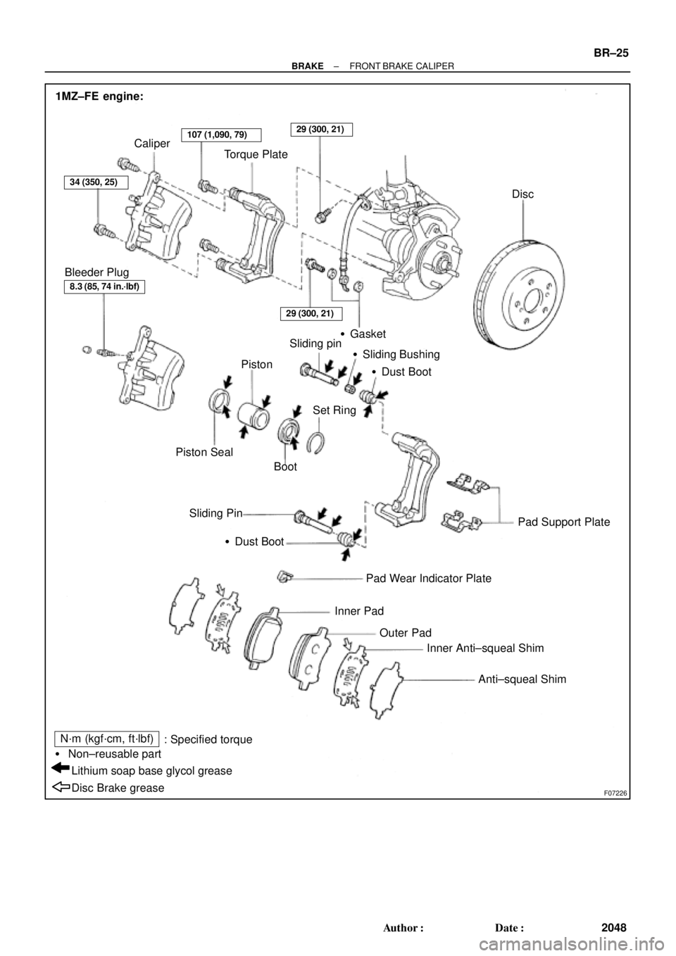
COMPONENTS
Page 1039 of 4592
F07226
1MZ±FE engine:
Caliper
Torque Plate
Disc
PistonSliding pin
�Sliding Bushing
�Dust Boot
Pad Support Plate Sliding Pin
�Dust Boot
Pad Wear Indicator Plate
Inner Pad Piston Seal
BootSet Ring
Outer Pad
Inner Anti±squeal Shim
Anti±squeal Shim
Disc Brake grease Lithium soap base glycol grease � Non±reusable part
N´m (kgf´cm, ft´lbf)
: Specified torque Bleeder Plug
34 (350, 25)
107 (1,090, 79)29 (300, 21)
8.3 (85, 74 in.´lbf)
29 (300, 21)
�Gasket
± BRAKEFRONT BRAKE CALIPER
BR±25
2048 Author�: Date�:
Page 1040 of 4592
BR0AR±03
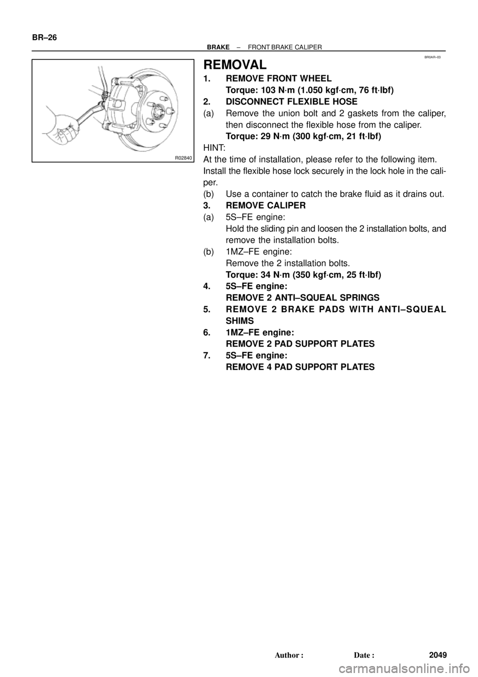
R02840
BR±26
± BRAKEFRONT BRAKE CALIPER
2049 Author�: Date�:
REMOVAL
1. REMOVE FRONT WHEEL
Torque: 103 N´m (1.050 kgf´cm, 76 ft´lbf)
2. DISCONNECT FLEXIBLE HOSE
(a) Remove the union bolt and 2 gaskets from the caliper,
then disconnect the flexible hose from the caliper.
Torque: 29 N´m (300 kgf´cm, 21 ft´lbf)
HINT:
At the time of installation, please refer to the following item.
Install the flexible hose lock securely in the lock hole in the cali-
per.
(b) Use a container to catch the brake fluid as it drains out.
3. REMOVE CALIPER
(a) 5S±FE engine:
Hold the sliding pin and loosen the 2 installation bolts, and
remove the installation bolts.
(b) 1MZ±FE engine:
Remove the 2 installation bolts.
Torque: 34 N´m (350 kgf´cm, 25 ft´lbf)
4. 5S±FE engine:
REMOVE 2 ANTI±SQUEAL SPRINGS
5. REMOVE 2 BRAKE PADS WITH ANTI±SQUEAL
SHIMS
6. 1MZ±FE engine:
REMOVE 2 PAD SUPPORT PLATES
7. 5S±FE engine:
REMOVE 4 PAD SUPPORT PLATES