Page 907 of 4592
BO0LV±01
H01812
Sliding Roof
Sliding Roof Glass
Sunroof Opening Trim
Headliner Assembly
Room Light
Map Light Assembly
± BODYSLIDING ROOF (TMMK Made)
BO±63
2411 Author�: Date�:
COMPONENTS
Page 913 of 4592

BO±69
2417 Author�: Date�:
6. VERIFY CORRECT INSTALLATION TIMING
(a) Cycle the unit once (vent p")
H01821
OK NG
H01822
Guide Pin Lift Arm Assembly
Slide Rail
H01823
Hook
± BODYSLIDING ROOF (TMMK Made)
BO±69
2417 Author�: Date�:
6. VERIFY CORRECT INSTALLATION TIMING
(a) Cycle the unit once (vent position closed, slide open, slide
completely closed).
HINT:
After cycling the unit closed from the slide open position, verify
the alignment holes in the cable arm and cam block are aligned
and the motor pointers are in the ºOº position.
The timing of the sliding roof is okay if the holes are within
1/2 a diameter of each other as shown when closed from
the ºside openº position.
NOTICE:
The holes will normally not align when moving the sliding
roof from the vent open position to the closed position.
(b) There should be a slight interference between the guide
pin and the curved ºlead±inº of the side rail. Confirm by
cycling the unit. A clicking sound from the hook indicates
the adjustment is incorrect.
If the guide pin has been disturbed, readjust as follows:
(1) Loosen the screw and adjust the pin so there is a
slight interference.
(2) Tighten the screw and cycle the unit.
(3) Confirm the hook smoothly engages the wind de-
flector spring.
(4) Repeat if necessary.
7. REINSTALL GLASS PANEL
Page 917 of 4592
N20951
A
Instrument Panel Wire Harness
No.1 Defroster Nozzle Garnish
Defroster Nozzle Assembly A
A
RH Side Defroster Duct Nozzle
No.1
Side Defroster
Duct Nozzle
A
A
A
A
A
ANo.2 Heater Duct to
Register
No.3 Instrument
Panel Register
Assembly K
K
K
K
K
K
No.1 Heater Duct to
RegisterAAA
No.1 Instrument Panel
Regigter AssemblyNo.2 Instrument
Panel Register
AssemblyInstrument
Panel Center
Bracket
Instrument PanelGlove Box
Light Assembly
± BODYINSTRUMENT PANEL
BO±73
2421 Author�: Date�:
Page 923 of 4592
BO0MD±01
N21124
± BODYINSTRUMENT PANEL
BO±79
2427 Author�: Date�:
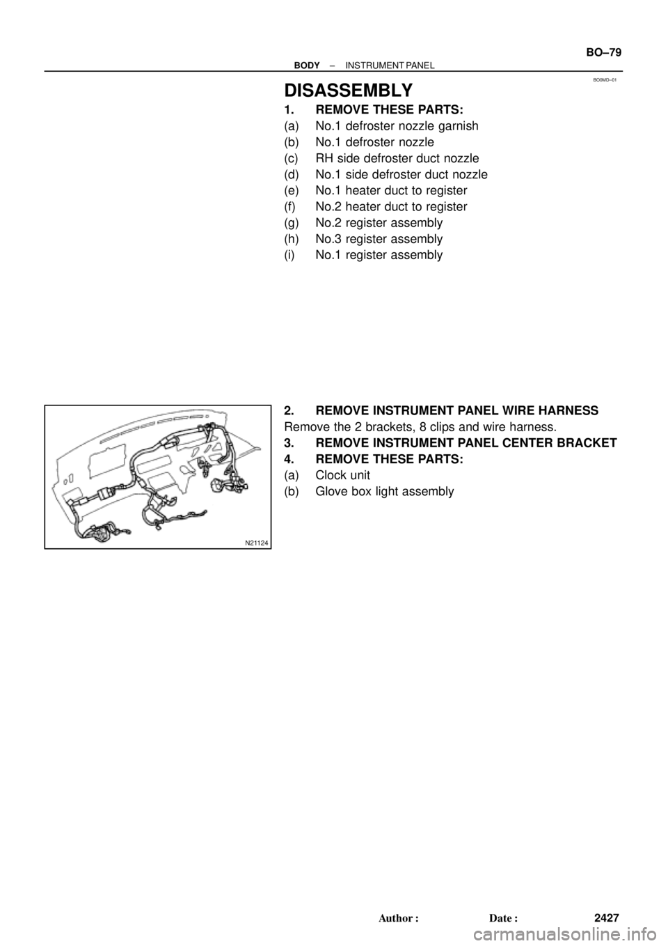
DISASSEMBLY
1. REMOVE THESE PARTS:
(a) No.1 defroster nozzle garnish
(b) No.1 defroster nozzle
(c) RH side defroster duct nozzle
(d) No.1 side defroster duct nozzle
(e) No.1 heater duct to register
(f) No.2 heater duct to register
(g) No.2 register assembly
(h) No.3 register assembly
(i) No.1 register assembly
2. REMOVE INSTRUMENT PANEL WIRE HARNESS
Remove the 2 brackets, 8 clips and wire harness.
3. REMOVE INSTRUMENT PANEL CENTER BRACKET
4. REMOVE THESE PARTS:
(a) Clock unit
(b) Glove box light assembly
Page 926 of 4592
BO0MG±01
N22600
Assist Grip
Sun VisorRoof Headlining
Assist Grip
Room Light Map Light
Assembly
Holder
Cover
Holder
Sun Visor
Center Pillar Garnish
Roof Side Inner Garnish Front Pillar Garnish
Front Door Scuff
PlateLower Center
Pillar GarnishRear Side Seat
Back RH
42 (420, 31)
Rear Seat
Side GarnishRear Seatback
Rear Side Seat
Back LH
42 (420, 31)
18 (185, 13)
18 (185, 13)
18 (185, 13)
Rear Seat Cushion
Center Pillar Garnish
42 (420, 31)
42 (420, 31)
Roof Seat
Side Garnish
Front Pillar Garnish
Rear Seat
Side Garnish
Lower Center
Pillar Garnish
42 (420, 31)
Front Door Scuff
Plate
N´m (kgf´cm, ft´lbf): Specified torque BO±82
± BODYROOF HEADLINING
2430 Author�: Date�:
ROOF HEADLINING
COMPONENTS
Page 927 of 4592
BO0MH±01
N21457
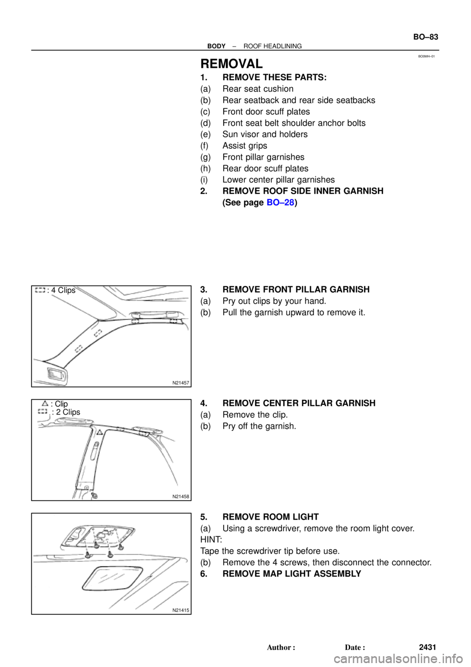
: 4 Clips
N21458
: Clip
: 2 Clips
N21415
± BODYROOF HEADLINING
BO±83
2431 Author�: Date�:
REMOVAL
1. REMOVE THESE PARTS:
(a) Rear seat cushion
(b) Rear seatback and rear side seatbacks
(c) Front door scuff plates
(d) Front seat belt shoulder anchor bolts
(e) Sun visor and holders
(f) Assist grips
(g) Front pillar garnishes
(h) Rear door scuff plates
(i) Lower center pillar garnishes
2. REMOVE ROOF SIDE INNER GARNISH
(See page BO±28)
3. REMOVE FRONT PILLAR GARNISH
(a) Pry out clips by your hand.
(b) Pull the garnish upward to remove it.
4. REMOVE CENTER PILLAR GARNISH
(a) Remove the clip.
(b) Pry off the garnish.
5. REMOVE ROOM LIGHT
(a) Using a screwdriver, remove the room light cover.
HINT:
Tape the screwdriver tip before use.
(b) Remove the 4 screws, then disconnect the connector.
6. REMOVE MAP LIGHT ASSEMBLY
Page 969 of 4592
 if it has been use")
BO0NG±01
BO0632
BO0633
15°
45° BO±124
± BODYSEAT BELT
2472 Author�: Date�:
INSPECTION
CAUTION:
Replace the seat belt assembly (outer belt, inner belt, bolts,
nuts or sill±bar) if it has been used in a severe impact. The
entire assembly should be replaced even if damage is not
obvious.
1. All Seat Belt:
RUNNING TEST (IN SAFE AREA)
(a) Fasten the front seat belts.
(b) Drive the car at 10 mph (16 km/h) and slam on the brakes.
Check that the belt locks and cannot be extended at this
time.
HINT:
Conduct this test in a safe area. If the belt does not lock, remove
the belt mechanism assembly and conduct the following static
check. Also, whenever installing a new belt assembly, verify the
proper operation before installation.
2. Driver 's Seat Belt (ELR):
STATIC TEST
(a) Make sure that the belt locks when pulled out quickly.
(b) Remove the locking retractor assembly.
(c) Tilt the retractor slowly.
(d) Make sure that the belt can be pulled out at a tilt of 15 de-
grees or less, and cannot be pulled out over 45 degrees
of tilt.
If a problem is found, replace the assembly.
3. Front RH Seat Belt and Rear Seat Belt (ALR/ELR):
STATIC TEST
(a) Make sure that the belt locks when pulled out quickly.
(b) Remove the locking retractor assembly.
(c) Pull out the whole belt and measure the length of the
whole belt.
Then retract the belt slightly and pull it out again
(d) Make sure that the belt cannot be extended further.
If a problem is found, replace the assembly.
Page 974 of 4592

AB0158
SSTBattery
AB0152
SST
AB0158
SSTBattery
H01580
SST
H01346
± BODYSEAT BELT PRETENSIONER
BO±129
2477 Author�: Date�:
1. SEAT BELT PRETENSIONER DEPLOYMENT WHEN
SCRAPPING VEHICLE
HINT:
Have a battery ready as the power source to deploy the airbag.
(a) Check functioning of SST
CAUTION:
When deploying the seat belt pretensioner, always use the
specified SST: SRS Airbag Deployment Tool.
SST 09082±00700, 09082±00740
(1) Connect the SST to battery.
Connect the red clip of the SST to the battery posi-
tive (+) terminal and the black clip to the battery neg-
ative (±) terminal.
HINT:
Do not connect the yellow connector which will be connected
with the seat belt pretensioner.
(2) Check functioning of SST
Press the SST activation switch, and check the LED
of the SST activation switch lights up.
CAUTION:
If the LED lights up when the activation switch is not being
pressed, SST malfunction is probable, so definitely do not
use the SST.
(b) Install the SST.
(1) Remove the front door scuff plate.
(2) Remove the center pillar lower garnish.
(3) Disconnect the pretensioner connector as shown in
the illustration.
(4) Buckle the front seat belt and check that there is no
looseness and slack in the front seat inner belt and
front seat outer belt.
SST 09082±00700, 09082±00740