Page 885 of 4592
 Using a heat light, heat the bo")
BO0MA±01
BO6675
N19058
H01884
Adhesive TapeAdhesive Tape
N22643
± BODYBODY OUTSIDE MOULDING
BO±41
2389 Author�: Date�:
INSTALLATION
1. HEAT BODY MOUNTING SURFACE
(a) Using a heat light, heat the body mounting surface to
40 ± 60 °C (104 ± 140 °F).
NOTICE:
Do not heat body excessively.
(b) Remove the adhesive tape from the body.
(c) Wipe off stains with cleaner.
2. CLEAN MOULDING
If reusing the moulding:
(a) Using a heat light, heat the moulding to 20 ± 30 °C (68 ±
86 °F).
NOTICE:
Do not heat moulding excessively.
(b) Remove the adhesive tape from the moulding.
(c) Wipe off stains with cleaner.
(d) Apply a new adhesive tape to moulding as shown in the
illustration.
3. INSTALL MOULDING
(a) Using a heat light, heat the body and moulding.
Body: 40 ± 60 °C (104 ± 140 °F)
Moulding: 20 ± 30 °C (68 ± 86 °F)
NOTICE:
Do not heat moulding excessively.
(b) Lift moulding release sheet from face of moulding.
NOTICE:
When the moulding release sheet is removed, make sure
that no dirt or dust can get onto the uncoated area.
(c) Align the bosses with their corresponding holes in the
body, and press firmly on the moulding. Refer to the il-
lustration for the front fender moulding application proce-
dures.
NOTICE:
Do not apply excessive force onto the moulding, but steady
pressure with your thumbs.
Page 886 of 4592
BO0LO±01
N20947
Front Pillar GarnishWeatherstripSun VisorInside Rear
View Mirror Map Light Assem-
bly
Sun Visor
Holder
Windshield
Glass
Windshield Upper Moulding
Weatherstrip Stopper
Dam
Windshield
Outside
Moulding
Wiper Arm
Cowl Louver RH
Weatherstrip
24 (245, 18)
Cowl Louver LHWindshield
Outside
MouldingFront Pillar Garnish
Hood
N´m (kgf´cm, ft´lbf): Specified torque BO±42
± BODYWINDSHIELD
2390 Author�: Date�:
WINDSHIELD
COMPONENTS
Page 887 of 4592
 Inner rear view mirror
(b) Sun visors and holders
(c) Map light assembly
(d) Front pilla")
BO0LP±01
N20982
N20983
BO5232
± BODYWINDSHIELD
BO±43
2391 Author�: Date�:
REMOVAL
1. REMOVE THESE PARTS:
(a) Inner rear view mirror
(b) Sun visors and holders
(c) Map light assembly
(d) Front pillar garnishes
(e) Hood
(f) Wiper arms
(g) Cowl louvers
(h) Weatherstrips
2. REMOVE WEATHERSTRIP
Remove the weatherstrip by pulling.
HINT:
Remove only the front half of weatherstrip.
3. REMOVE WINDSHIELD OUTSIDE MOULDING
(a) Using a drill of less than ù 5.0 mm (0.20 in.), drill out the
rivet heads and remove the moulding.
(b) Using a vacuum cleaner, remove the drill rivet and their
dust from the inside of the door.
CAUTION:
The cut rivet and rivet cutter will be not, avoid touching
them.
NOTICE:
Do not jiggle the rivet cutter while cutting.You may enlarge
the rivet hole or damage the rivet cutter.
HINT:
Do not drill the body.
Sealant may cause the moulding to stick to the glass. If neces-
sary, separate from the glass using a knife.
4. REMOVE WINDSHIELD UPPER MOULDING
Using a knife, cut off the moulding as shown.
NOTICE:
Do not damage the body with the knife.
5. REMOVE WINDSHIELD GLASS
(a) Push piano wire through between the body and glass
from the interior.
(b) Tie both wire ends to a wooden block or a similar object.
HINT:
Apply adhesive tape to the outer surface to prevent scratching.
Page 892 of 4592
N22592
N20984
N15432
20 mm
(0.79 in.)
BO±48
± BODYWINDSHIELD
2396 Author�: Date�:
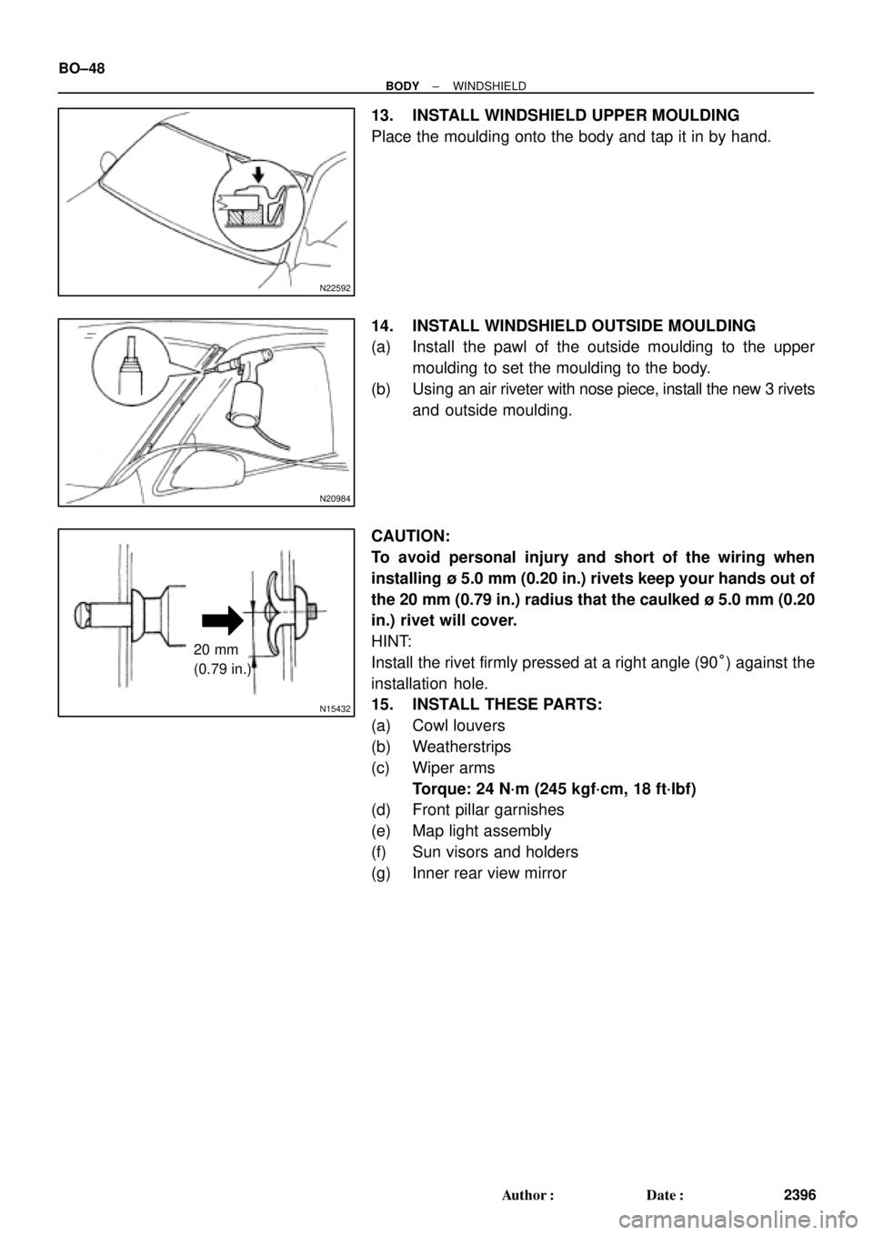
13. INSTALL WINDSHIELD UPPER MOULDING
Place the moulding onto the body and tap it in by hand.
14. INSTALL WINDSHIELD OUTSIDE MOULDING
(a) Install the pawl of the outside moulding to the upper
moulding to set the moulding to the body.
(b) Using an air riveter with nose piece, install the new 3 rivets
and outside moulding.
CAUTION:
To avoid personal injury and short of the wiring when
installing ù 5.0 mm (0.20 in.) rivets keep your hands out of
the 20 mm (0.79 in.) radius that the caulked ù 5.0 mm (0.20
in.) rivet will cover.
HINT:
Install the rivet firmly pressed at a right angle (90°) against the
installation hole.
15. INSTALL THESE PARTS:
(a) Cowl louvers
(b) Weatherstrips
(c) Wiper arms
Torque: 24 N´m (245 kgf´cm, 18 ft´lbf)
(d) Front pillar garnishes
(e) Map light assembly
(f) Sun visors and holders
(g) Inner rear view mirror
Page 893 of 4592
BO0LR±01
N20948
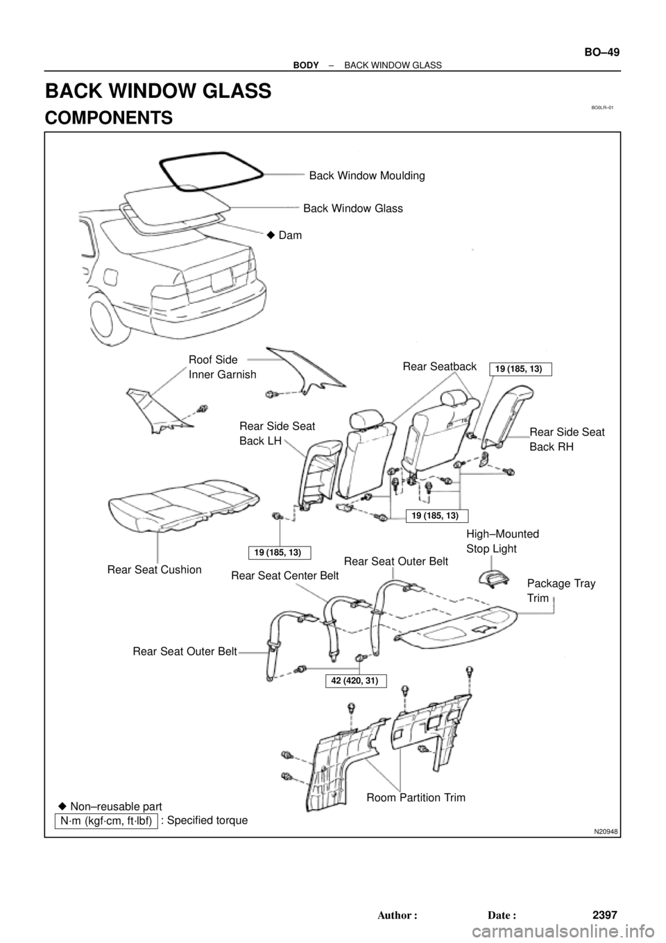
Back Window Moulding
Back Window Glass
� Dam
Roof Side
Inner GarnishRear Seatback
19 (185, 13)
42 (420, 31)
Rear Side Seat
Back RH Rear Side Seat
Back LH
Rear Seat Cushion
19 (185, 13)
19 (185, 13)
Rear Seat Center BeltRear Seat Outer BeltHigh±Mounted
Stop Light
Package Tray
Trim
Rear Seat Outer Belt
Room Partition Trim
� Non±reusable part
N´m (kgf´cm, ft´lbf): Specified torque
± BODYBACK WINDOW GLASS
BO±49
2397 Author�: Date�:
BACK WINDOW GLASS
COMPONENTS
Page 894 of 4592

BO0LS±01
N21020
3 Clips
1 Clip
N22588
N21021
4 Clips
N21121
N20985
BO±50
± BODYBACK WINDOW GLASS
2398 Author�: Date�:
REMOVAL
1. REMOVE REAR SEAT CUSHION AND SEATBACKS
2. REMOVE ROOF SIDE INNER GARNISHES
(a) Remove the clips.
(b) Pull the garnish to remove it.
3. REMOVE HIGH±MOUNTED STOP LIGHT
(a) Push on the both side of the cover to release the claws by
your hand and remove the cover as shown in the illustra-
tion.
(b) Remove the 2 bolts and stop light, then disconnect the
connector.
4. REMOVE PACKAGE TRAY TRIM
(a) Remove the bolts holding the rear seat belt lower side to
the body.
(b) Remove the seat belts with seat belt hole covers from the
package trim.
(c) Remove the trim by pulling forward.
5. REMOVE ROOM PARTITION TRIMS
Remove the 6 clips and room partition trims.
6. REMOVE THESE PARTS
(a) Assist grips.
(b) Rear side of roof headlining.
7. DISCONNECT DEFOGGER WIRE CONNECTORS
8. REMOVE BACK WINDOW MOULDING
Using a knife, cut off the moulding as shown.
NOTICE:
Do not damage the body with the knife.
9. REMOVE BACK WINDOW GLASS
Remove the glass in the same way as windshield.
(See page BO±43)
Page 896 of 4592
BO±52
± BODYBACK WINDOW GLASS
2400 Author�: Date�:
(d) Room partition trims
(e) Seat belt lower side bolts
Torque: 42 N´m (420 kgf´cm, 31 ft´lbf)
(f) High±mounted stop light
(g) Roof side inner garnish
(h) Rear seatbacks and seat cushion
Torque: 18 N´m (185 kgf´cm, 13 ft´lbf)
Page 906 of 4592
H01814
BO0LU±01
H01815
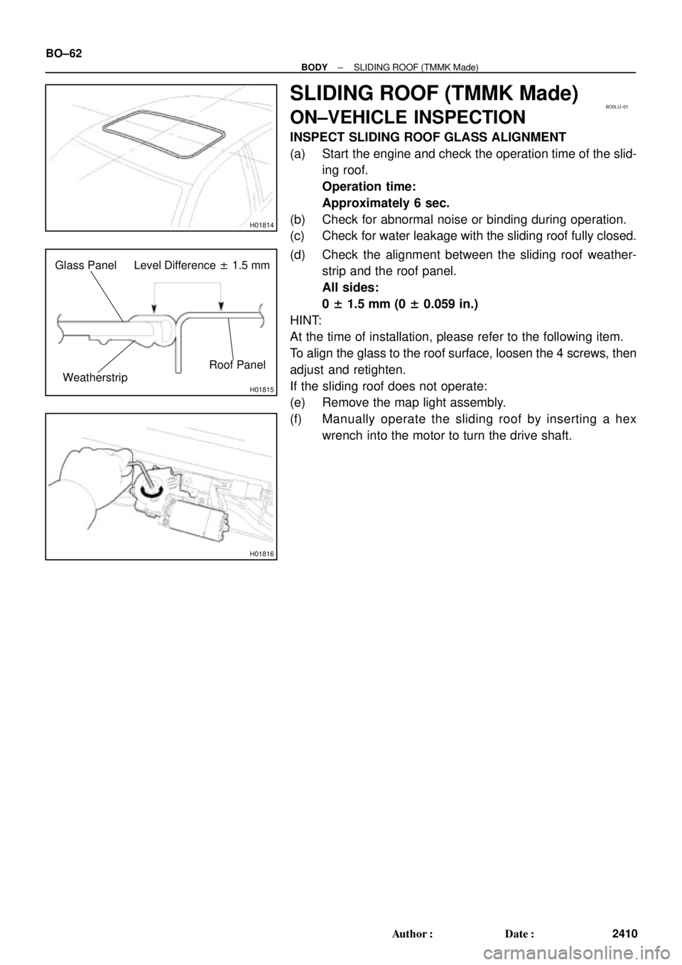
Glass Panel Level Difference ± 1.5 mm
Roof Panel
Weatherstrip
H01816
BO±62
± BODYSLIDING ROOF (TMMK Made)
2410 Author�: Date�:
SLIDING ROOF (TMMK Made)
ON±VEHICLE INSPECTION
INSPECT SLIDING ROOF GLASS ALIGNMENT
(a) Start the engine and check the operation time of the slid-
ing roof.
Operation time:
Approximately 6 sec.
(b) Check for abnormal noise or binding during operation.
(c) Check for water leakage with the sliding roof fully closed.
(d) Check the alignment between the sliding roof weather-
strip and the roof panel.
All sides:
0 ± 1.5 mm (0 ± 0.059 in.)
HINT:
At the time of installation, please refer to the following item.
To align the glass to the roof surface, loosen the 4 screws, then
adjust and retighten.
If the sliding roof does not operate:
(e) Remove the map light assembly.
(f) Manually operate the sliding roof by inserting a hex
wrench into the motor to turn the drive shaft.