Page 836 of 4592

1.2 Sec.
0.8 Sec.
0.25 Sec. 0.5 Sec.0.25 Sec.
1 Sec. Blinks Code 2±1 Code2±2
0.25 Sec.
0.25 Sec.0.5 Sec. 1 Sec. BE±120
± BODY ELECTRICALENGINE IMMOBILISER SYSTEM
2340 Author�: Date�:
HINT:
�When a key is not inserted in the key cylinder in the automatic registration mode, the security indicator
always lights on.
�When the immobiliser system operations normally and the key is pull out, the security indicator blinks.
�When key code registration could not be performed in the automatic registration mode, code 2±1 is
output from the security indicator and when inserting the already registered key, code 2±2 is output.
(b) Automatic registration mode completion
If completing the mode forcibly when more than 1 key code have been registered in the automatic reg-
istration mode, perform the following procedures.
After 1 more key code have been registered with master key, perform step (1) or (2) without pulling
the key out or inserting the already registered key.
(1) Depress and release brake pedal 5 times or more within 15sec.
(2) With the TOYOTA hand±held tester, require automatic registration mode completion.
Page 848 of 4592
BO0KV±01
H01708
Turn Signal Light Assembly
Upper Reinforcement
Sub±AssemblyTurn Signal Light Assembly
Fender Liner Front Bumper
Reinforcement
Energy Absorber
Mounting Plate
Front Bumper
Energy Absorber
Engine Under Cover Bumper Cover Emblem,
Radiator GrillFender Liner
N´m (kgf´cm, ft´lbf) : Specified torque
5.5 (55, 49 in.´lbf)34 (350, 25)
Clip
34 (350, 25)
No.2
Reinforcement
Clip BO±4
± BODYFRONT BUMPER
2352 Author�: Date�:
FRONT BUMPER
COMPONENTS
Page 849 of 4592
BO0KW±01
H01709
H01710
H01711
H01712
± BODYFRONT BUMPER
BO±5
2353 Author�: Date�:
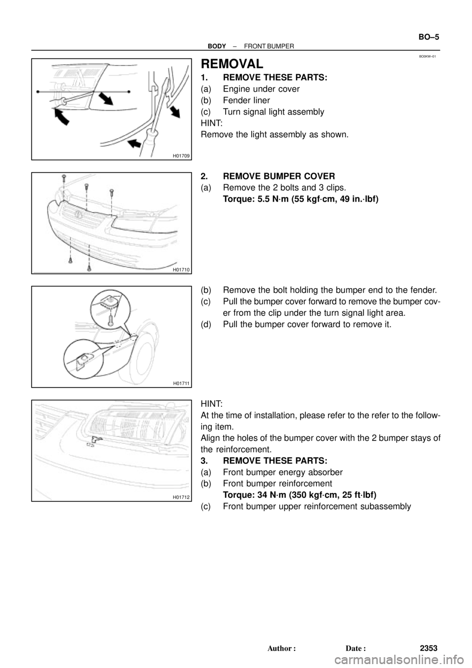
REMOVAL
1. REMOVE THESE PARTS:
(a) Engine under cover
(b) Fender liner
(c) Turn signal light assembly
HINT:
Remove the light assembly as shown.
2. REMOVE BUMPER COVER
(a) Remove the 2 bolts and 3 clips.
Torque: 5.5 N´m (55 kgf´cm, 49 in.´lbf)
(b) Remove the bolt holding the bumper end to the fender.
(c) Pull the bumper cover forward to remove the bumper cov-
er from the clip under the turn signal light area.
(d) Pull the bumper cover forward to remove it.
HINT:
At the time of installation, please refer to the refer to the follow-
ing item.
Align the holes of the bumper cover with the 2 bumper stays of
the reinforcement.
3. REMOVE THESE PARTS:
(a) Front bumper energy absorber
(b) Front bumper reinforcement
Torque: 34 N´m (350 kgf´cm, 25 ft´lbf)
(c) Front bumper upper reinforcement subassembly
Page 871 of 4592
BO0LD±01
H01747
Torsion Bar
Luggage Compart-
ment Door Hinge
Luggage Compart-
ment Door Hinge
Luggage Compartment
Door
Luggage Compartment
Door Trim
Left Side Luggage
Trim
Finish Side Trim
Rear Luggage Trim
Rear Seat CushionRoom Partition TrimPackage Tray Trim
High Mounted
Stop Light
Rear SeatbackFinish Side Trim Door Lock
Door Lock StrikerLeft Hand Back
Up LightRight Hand
Back Up Light Right Side Luggage
Trim
: Specified torque
N´m (kgf´cm, ft´lbf)
Lock Cylinder
Luggage Compart-
ment Floor Mat
8.0 (80, 71 in.´lbf)
8.0 (80, 71 in.´lbf)
5.5 (55, 49 in.´lbf)
5.5 (55, 49 in.´lbf)
± BODYLUGGAGE COMPARTMENT DOOR AND HINGE
BO±27
2375 Author�: Date�:
LUGGAGE COMPARTMENT DOOR AND HINGE
COMPONENTS
Page 872 of 4592

BO0LE±01
N22588
121
N21430
: 4 Clips
N22591
BO±28
± BODYLUGGAGE COMPARTMENT DOOR AND HINGE
2376 Author�: Date�:
REMOVAL
1. REMOVE LUGGAGE COMPARTMENT DOOR TRIM
2. REMOVE LUGGAGE COMPARTMENT DOOR
(a) Disconnect the connector.
(b) Using a clip remover, disconnect the clamps.
(c) Remove the 4 bolts and door.
Torque: 8.0 N´m (80 kgf´cm, 71 in.´lbf)
3. REMOVE THESE PARTS:
(a) Luggage compartment floor mat
(b) LH and RH rear floor finish side plates
(c) Inner cover trims
(d) Rear seat
(e) Room partition trims
4. REMOVE HIGH±MOUNTED STOP LIGHT
(a) Push on the both side of the cover to release the claws by
your hand and remove the cover as shown in the illustra-
tion.
(b) Remove the 2 bolts and stop light, then disconnect the
connector.
5. REMOVE ROOF SIDE INNER GARNISH
(a) Remove the clip.
(b) Using a screwdriver, pry loose and remove the garnish.
HINT:
Tape the screwdriver tip before use.
6. REMOVE PACKAGE TRAY TRIM
7. REMOVE TORSION BAR
(a) Remove the torsion bar from the center bracket.
Page 874 of 4592
BO0LF±01
BO±30
± BODYLUGGAGE COMPARTMENT DOOR AND HINGE
2378 Author�: Date�:
DISASSEMBLY
1. REMOVE DOOR LOCK
(a) Disconnect the control link.
(b) Remove the 2 bolts and lock.
Torque: 5.5 N´m (56 kgf´cm, 49 in.´lbf)
2. REMOVE REAR COMBINATION LIGHT
(a) Disconnect the connector.
(b) Remove the 10 nuts and rear combination lights.
Page 877 of 4592
 Insert the torsion bar into the bracket.
H")
BO0LI±01
H01754
H01755
H01756
N21430
: 4 clips
± BODYLUGGAGE COMPARTMENT DOOR AND HINGE
BO±33
2381 Author�: Date�:
INSTALLATION
1. INSTALL TORSION BAR
(a) Insert the torsion bar into the bracket.
HINT:
The center bracket opening is the nominal position of the tor-
sion bar.
If needed, move the torsion bar to the upper or lower hole to pro-
vide the correct luggage door lift.
(b) Install the SST onto the torsion bar of the hinge side.
SST 09804±24010
(c) Slowly lift the torsion bar with the SST and place it in the
torsion bar bracket.
(d) Slowly push the SST down and install the torsion bar to
the hinge.
(e) Slowly lift the SST and install the torsion bar.
(f) Install the torsion bar to the center bracket.
(g) Repeat for the other side.
2. INSTALL PACKAGE TRAY TRIM
3. INSTALL ROOF SIDE INNER GARNISH
4. INSTALL HIGH MOUNTED STOP LIGHT
5. INSTALL THESE PARTS:
(a) Room partition trims
(b) Rear seat
(c) Inner cover trims
(d) LH and RH rear floor finish side plates
(e) Luggage compartment floor mat
6. INSTALL LUGGAGE COMPARTMENT DOOR
(a) Install the door with 4 bolts.
(b) Install clamps.
(c) Connect the connector.
7. INSTALL LUGGAGE COMPARTMENT DOOR TRIM
Page 884 of 4592
BO0M9±01
H01782
H01783
BO±40
± BODYBODY OUTSIDE MOULDING
2388 Author�: Date�:
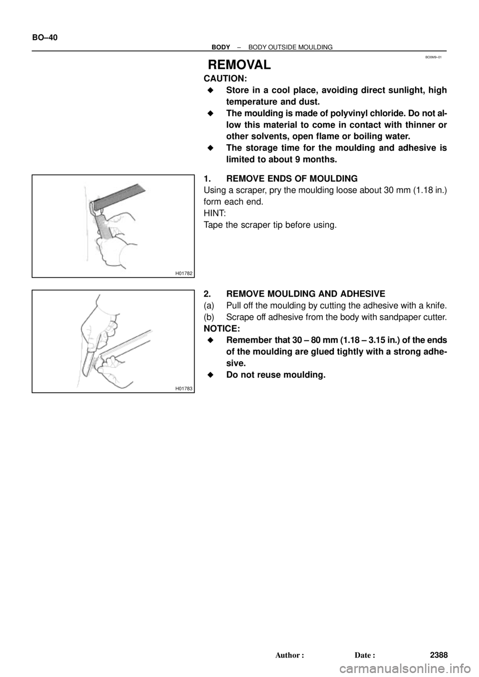
REMOVAL
CAUTION:
�Store in a cool place, avoiding direct sunlight, high
temperature and dust.
�The moulding is made of polyvinyl chloride. Do not al-
low this material to come in contact with thinner or
other solvents, open flame or boiling water.
�The storage time for the moulding and adhesive is
limited to about 9 months.
1. REMOVE ENDS OF MOULDING
Using a scraper, pry the moulding loose about 30 mm (1.18 in.)
form each end.
HINT:
Tape the scraper tip before using.
2. REMOVE MOULDING AND ADHESIVE
(a) Pull off the moulding by cutting the adhesive with a knife.
(b) Scrape off adhesive from the body with sandpaper cutter.
NOTICE:
�Remember that 30 ± 80 mm (1.18 ± 3.15 in.) of the ends
of the moulding are glued tightly with a strong adhe-
sive.
�Do not reuse moulding.