Page 986 of 4592

I07709
Slide
rheostat35.63 ±
0.1 W35.63 ±
0.1 W
Z14205
Warning Light
Ignition
Switch
Battery
1
N06640
± BODY ELECTRICALCOMBINATION METER
BE±7
8. INSPECT ENGINE COOLANT TEMPERATURE SEND-
ER GAUGE RESISTANCE
Connect the wire harness as shown in the illustration, and ad-
just the ammeter pointer to indicate º0º using the slide rheostat,
then read the rheostat indication.
Temperature °C (°F)Resistance (W)
50 (122.0)160 ± 240
120 (248.0)17.1 ± 21.2
If resistance value is not as specified, replace the engine cool-
ant temperature sender gauge.
9. INSPECT LOW OIL PRESSURE WARNING LIGHT
(a) Disconnect the connector from the warning switch and
ground terminal on the wire harness side connector.
(b) Turn the ignition switch ON and check that the warning
light lights up.
If the warning light does not light up, test the bulb.
10. INSPECT LOW OIL PRESSURE SWITCH
(a) Disconnect the connector from the switch.
(b) Check that continuity exists between terminal and ground
with the engine stopped.
(c) Check that no continuity exists between terminal and
ground with the engine running.
HINT:
Oil pressure should be over 24.5 kPa (0.25 kgf/cm
2, 3.55 psi).
If operation is not as specified, replace the switch.
Page 991 of 4592

BO2DO±02
H09250
Luggage Compartment
Door HingeLuggage Compartment DoorLuggage Compartment
Door Hinge
Door Lock Cylinder
Door Lock StrikerDoor Lock
Door Support
Inner Luggage Compartment
Trim Cover
Spare Wheel
Rear SeatbackSpare Wheel Cover
Spare Wheel
Carrier
Spare Wheel
Carrier Spacer
Luggage Compartment
Trim Front Cover
Rear Floor Finish
Side Plate
Rear Seat Outer BeltInner Lower Luggage
Compartment Trim Cover
Rear Seat Outer Belt Rear Floor Finish
Side Plate
Rear Seat CushionRoof Side
Inner Garnish
No. 1 Upper Back Panel Hole CoverPackage Tray Trim High±mounted
Stop Light
Roof Side
Inner Garnish
41 (420, 31)
41 (420, 31)
7.8 (80, 69 in.´lbf)
5.4 (55, 49 in.´lbf)
Luggage Compartment Door Cover
x11
N´m (kgf´cm, ft´lbf) : Specified TorqueReat Combination Light
22 (224, 16)
22 (224, 16)
5.4 (55, 49 in.´lbf)
18 (185, 13)
7.8 (80, 69 in.´lbf)
22 (224, 16)
Rear Floor
Finish Plate
± BODYLUGGAGE COMPARTMENT DOOR AND HINGE
BO±5
544 Author�: Date�:
LUGGAGE COMPARTMENT DOOR AND HINGE
COMPONENTS
Page 993 of 4592
 Using a clip remover, remove the 2 clips.
HINT:
Tape the")
H092532 Clips
H09254
3 Clips
Clip
H09255
2
1 1
H07599
2
1
± BODYLUGGAGE COMPARTMENT DOOR AND HINGE
BO±7
8. REMOVE REAR FLOOR FINISH PLATE
(a) Using a clip remover, remove the 2 clips.
HINT:
Tape the screwdriver tip before use.
(b) Insert a screwdriver between the rear floor finish plate and
body to pry out the rear floor finish plate.
HINT:
Tape the screwdriver tip before use.
9. REMOVE REAR SEAT CUSHION AND SEATBACK
(See page BO±22)
10. REMOVE ROOF SIDE INNER GARNISH
(a) Using a clip remover, remove the clip.
(b) Insert a screwdriver between the roof side inner garnish
and body to pry it out.
HINT:
Tape the screwdriver tip before use.
(c) Employ the same manner described above to the other
side.
11. REMOVE HIGH±MOUNTED STOP LIGHT
Remove the high±mounted stop light as shown in the illustra-
tion, then disconnect the connector.
12. REMOVE PACKAGE TRAY TRIM
(a) Remove the bolts and rear seat outer belt floor anchors.
Torque: 41 N´m (420 kgf´cm, 31 ft´lbf)
(b) Using a screwdriver, remove the seat belt bezels from the
package tray trim.
HINT:
Tape the screwdriver tip before use.
(c) Using a hexagon wrench, remove the 2 hexagon screws.
(d) Remove the package tray trim, then disconnect the con-
nectors.
HINT:
Remove the package tray trim through out the rear seat outer
belt floor anchors from the hole in the package tray trim.
13. REMOVE NO. 1 UPPER BACK PANEL HOLE COVER
Remove the 2 clips and No. 1 upper back panel hole cover.
14. REMOVE LUGGAGE COMPARTMENT DOOR SUP-
PORTS
Remove the 4 bolts and luggage compartment door support.
Torque: 22 N´m (224 kgf´cm, 16 ft´lbf)
15. REMOVE LUGGAGE COMPARTMENT DOOR HINGES
Remove the pins and luggage compartment door hinges.
Page 994 of 4592
BO2DQ±01
BO±8
± BODYLUGGAGE COMPARTMENT DOOR AND HINGE
DISASSEMBLY
1. REMOVE DOOR LOCK
(a) Disconnect the control link.
(b) Remove the 2 bolts and door lock.
Torque: 5.4 N´m (55 kgf´cm, 49 in.´lbf)
2. REMOVE REAR COMBINATION LIGHTS
(a) Disconnect the connectors.
(b) Remove the 6 nuts and rear combination lights.
3. REMOVE DOOR LOCK CYLINDER
Remove the 2 bolts and door lock cylinder.
Torque: 5.4 N´m (55 kgf´cm, 49 in.´lbf)
Page 1000 of 4592
BO2E2±01
H09257
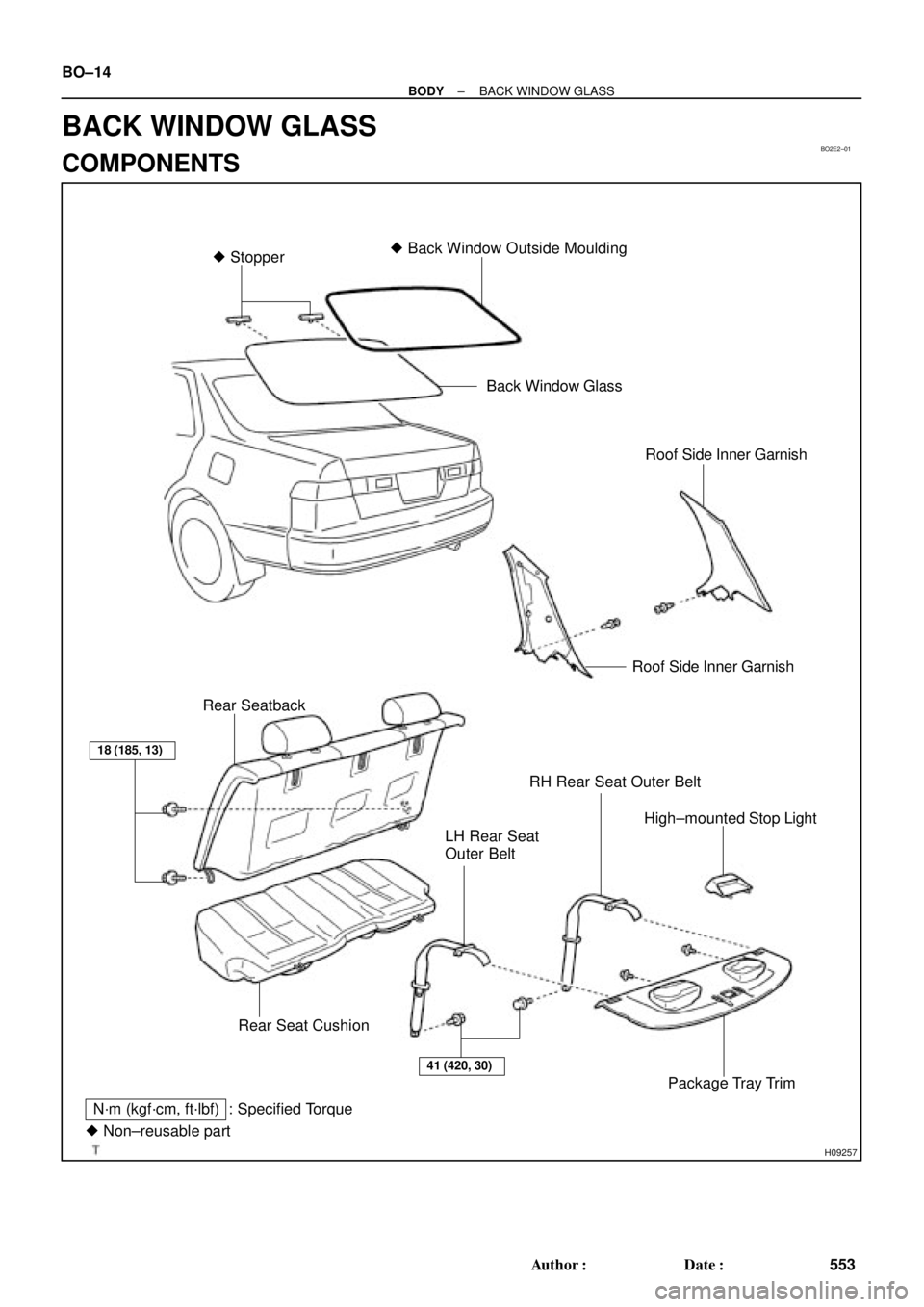
N´m (kgf´cm, ft´lbf) : Specified Torque� Stopper� Back Window Outside Moulding
High±mounted Stop Light Rear SeatbackBack Window Glass
Roof Side Inner Garnish
Package Tray Trim
Rear Seat Cushion
Roof Side Inner Garnish
� Non±reusable part
18 (185, 13)
LH Rear Seat
Outer Belt
41 (420, 30)
RH Rear Seat Outer Belt
BO±14
± BODYBACK WINDOW GLASS
553 Author�: Date�:
BACK WINDOW GLASS
COMPONENTS
Page 1001 of 4592

2. REMOVE ROOF SIDE INNER GARNISH
(a) Us")
BO2E3±01
H09254
3 Clips
Clip
H09255
2
1 1
H07599
2
1
N20985
± BODYBACK WINDOW GLASS
BO±15
REMOVAL
1. REMOVE REAR SEAT CUSHION AND SEATBACK
(See page BO±22)
2. REMOVE ROOF SIDE INNER GARNISH
(a) Using a clip remover, remove the clip.
(b) Insert a screwdriver between the roof side inner garnish
and body to pry it out.
HINT:
Tape the screwdriver tip before use.
(c) Employ the same manner described above to the other
side.
3. REMOVE HIGH±MOUNTED STOP LIGHT
Remove the high±mounted stop light as shown in the illustra-
tion, then disconnect the connector.
4. REMOVE PACKAGE TRAY TRIM
(a) Remove the bolts and rear seat belt floor anchors.
(b) Using a screwdriver, remove the seat belt bezels from the
package tray trim.
HINT:
Tape the screwdriver tip before use.
(c) Using a hexagon wrench, remove the 2 hexagon screws.
(d) Remove the package tray trim, then disconnect the con-
nectors.
HINT:
Remove the package tray trim through out the rear seat outer
belt floor anchors from the hole in the package tray trim.
5. REMOVE BACK WINDOW OUTSIDE MOULDING
(a) Using a knife, cut off the moulding as shown in the illustra-
tion.
NOTICE:
Do not damage the body with the knife.
(b) Remove the remaining moulding.
Page 1006 of 4592
H09254
3 Clips
Clip BO±20
± BODYBACK WINDOW GLASS
14. INSTALL PACKAGE TRAY TRIM
(a) Connect the connectors.
(b) Install the package tray trim with the 2 screws.
HINT:
Before installing the package tray trim pass the rear seat outer
belt floor anchor through the hole in the package tray trim.
15. INSTALL HIGH±MOUNTED STOP LIGHT
16. INSTALL ROOF SIDE INNER GARNISH
(a) Install the roof side inner garnish with clip.
(b) Employ the same manner described above to the other
side.
17. INSTALL REAR SEAT CUSHION AND SEATBACK
(See page BO±25)
Page 1013 of 4592
 if it has been used in a severe im-
pact")
BO2E1±01
BO0632
BO0633
15°
45°
± BODYSEAT BELT
BO±27
INSPECTION
CAUTION:
Replace the seat belt assembly (Outer belt, inner belt,
bolts, nuts or sill±bar) if it has been used in a severe im-
pact. The entire assembly should be replaced even if dam-
age is not obvious.
1. All seat belt:
RUNNING TEST IN SAFE AREA
(a) Fasten the front seat belts.
(b) Drive the car at 10 m/h (16 km/h) and slam on the brakes.
Check that the belt locks and cannot be extended at this
time.
HINT:
Conduct this test in a safe area. If the belt does not lock, remove
the belt mechanism assembly and conduct the following static
check. Also whenever installing a new belt assembly, verify the
proper operation before installation.
2. Driver 's seat belt (ELR):
STATIC TEST
(a) Make sure that the belt locks when pulled out quickly.
(b) Remove the locking retractor assembly.
(c) Tilt the retractor slowly.
(d) Make sure that the belt can be pulled out at a tilt of 15 de-
grees or less, and cannot be pulled out over 45 degrees
of tilt.
If a problem is found, replace the assembly.
3. Except driver's seat belt (ALR/ELR):
STATIC TEST
(a) Make sure that the belt locks when pulled out quickly.
(b) Remove the locking retractor assembly.
(c) Pull out the whole belt and measure the length of the
whole belt. Then retract the belt slightly and pull it out
again.
(d) Make sure that the belt cannot be extended further.
If a problem is found, replace the assembly.
 Disconnect the control link.
(b) Remove the 2 bolts and door lock.
Torque: 5.4 N´m (55 kgf´cm, 49 in.´l")
 Connect the connectors.
(b) Install the package tray trim with the 2 screws.
HINT:
Before installing the package t")