Page 1190 of 4592
CO03N±03
B06399
Radiator
No.1 ECT Switch
No.2 Cooling Fan Connector
Upper Radiator Support Upper Radiator Hose
No.1 Cooling Fan Connector
No.1 ECT Switch Wire Connector Radiator Assembly
Lower Radiator
Support� O±Ring
A/T Oil Cooler Hose
Relay Block
(for Daytime Running Light System) No.1 ECT Switch Wire No.1 Cooling FanNo.2 Cooling Fan
Upper Radiator Support
Lower Radiator
Support
� Non±reusable part� O±Ring Drain PlugLower
Radiator
Hose A/T Oil Cooler Hose
Lower Radiator Hose CO±16
± COOLING (1MZ±FE)RADIATOR
1624 Author�: Date�:
COMPONENTS
Page 1192 of 4592
RADIATOR
1626 Author�: Date�:
REMOVAL
HINT:
�At the time of installation, please refer to the following
items.
�Start the")
CO03O±03
S04725
B05937
Lower
Hose
Oil
Cooler
Hose
CO±18
± COOLING (1MZ±FE)RADIATOR
1626 Author�: Date�:
REMOVAL
HINT:
�At the time of installation, please refer to the following
items.
�Start the engine, and check for coolant and A/T fluid
leaks.
�Check the A/T fluid level. (See page DI±438)
1. DRAIN ENGINE COOLANT
2. CANADA:
DISCONNECT RELAY BLOCK (FOR DAYTIME
RUNNING LIGHT SYSTEM) FROM BATTERY
HOLD±DOWN CLAMP
3. DISCONNECT UPPER RADIATOR HOSE FROM
RADIATOR
4. DISCONNECT LOWER RADIATOR HOSE FROM
WATER INLET PIPE
5. DISCONNECT A/T OIL COOLER HOSES FROM OIL
COOLER PIPES
6. DISCONNECT NO.1 AND NO.2 COOLING FAN
CONNECTORS
7. DISCONNECT NO.1 ECT SWITCH WIRE CONNECTOR
8. REMOVE RADIATOR AND COOLING FANS
ASSEMBLY
(a) Remove the 2 bolts and 2 upper supports.
Torque: 12.8 N´m (130 kgf´cm, 9 ft´lbf)
(b) Lift out the radiator, and remove the radiator and cooling
fans assembly.
(c) Remove the 2 lower supports.
9. REMOVE A/T OIL COOLER HOSES FROM
RADIATOR
10. REMOVE LOWER RADIATOR HOSE FROM
RADIATOR
Page 1194 of 4592
RADIATOR
1628 Author�: Date�:
DISA")
CO03P±03
CO1205Overhaul HandleStopper Bolt Dimension ºBº
ClawPart ºAº
SST
S04737Stopper BoltLock Plate
SSTTank
S04738
Ta p
Z18546
A/T CO±20
± COOLING (1MZ±FE)RADIATOR
1628 Author�: Date�:
DISASSEMBLY
1. REMOVE CUSHION FROM RADIATOR
2. ASSEMBLE SST
SST 09230±01010
(a) Install the claw to the overhaul handle, inserting it in the
hole in part ºAº as shown in the diagram.
(b) While gripping the handle, adjust the stopper bolt so that
dimension ºBº shown in the diagram is 0.2 ± 0.5 mm
(0.008 ± 0.020 in.).
NOTICE:
If this adjustment is not done, the claw may be damaged.
3. UNCAULK LOCK PLATES
Using SST to release the caulking, squeeze the handle until
stopped by the stopper bolt.
SST 09230±01010
4. REMOVE TANKS AND O±RINGS
(a) Lightly tap the bracket of the radiator (or radiator hose in-
let or outlet) with a soft±faced hammer and remove the
tank.
(b) Remove the O±ring.
5. A/T:
REMOVE OIL COOLER FROM LOWER TANK
(a) Remove the pipe.
(b) Remove the nuts and plate washers.
(c) Remove the oil cooler and O±rings.
Page 1195 of 4592

(2)
(3)(4)(5) (6)
CO1267
Lock Plate
Lock Plate
Core
CO0317
O±Ring� Normal
X Twisted
X Twisted
± COOLING (1MZ±FE)RADIATOR
CO±21
1629 Author�: Date�:
REASSEMBLY
1. A/T:
INST")
CO03Q±03
Z18506
A/T
(1)
(2)
(3)(4)(5) (6)
CO1267
Lock Plate
Lock Plate
Core
CO0317
O±Ring� Normal
X Twisted
X Twisted
± COOLING (1MZ±FE)RADIATOR
CO±21
1629 Author�: Date�:
REASSEMBLY
1. A/T:
INSTALL OIL COOLER TO LOWER TANK
(a) Clean the O±ring contact surface of the lower tank and oil
cooler.
(b) Install a new O±rings (1) to the oil cooler (2).
(c) Install the oil cooler with the O±rings to the lower tank (3).
(d) Install the plate washers (4), and nuts (5). Torque the
nuts.
Torque: 8.3 N´m (85 kgf´cm, 74 in.´lbf)
(e) Install the pipe (6).
Torque: 14.7 N´m (150 kgf´cm, 11 ft´lbf)
2. INSPECT LOCK PLATE
Inspect the lock plate for damage.
HINT:
�If the sides of the lock plate groove are deformed, reas-
sembly of the tank will be impossible.
�Therefore, first correct any deformation with pliers or simi-
lar object. Water leakage will result if the bottom of the
lock plate groove is damaged or dented, Therefore, repair
or replace if necessary.
NOTICE:
The radiator can only be recaulked 2 times. After the 2nd
time, the radiator core must be replaced.
3. INSTALL NEW O±RINGS AND TANKS
(a) After checking that there are no foreign objects in the lock
plate groove, install the new O±ring without twisting it.
HINT:
When cleaning the lock plate groove, lightly rub it with sand pa-
per without scratching it.
Page 1196 of 4592

S04736
Ta pCORRECT
WRONGTank
Lock
Plate
CO1206
Dimension ºBº
Stopper Bolt Part ºAº
Punch Assembly Overhaul HandleSST
S04739
13
2 5
47
68
Stopper
BoltSST
Tank
Lock
Plate
S04734
Rib
Bracket CO±22
± COOLING (1MZ±FE)RADIATOR
1630 Author�: Date�:
(b) Install the tank without damaging the O±ring.
(c) Tap the lock plate with a soft±faced hammer so that there
is no gap between it and the tank.
4. ASSEMBLE SST
SST 09230±01010, 09231±14010
(a) Install the punch assembly to the overhaul handle, insert-
ing it in the hole in part ºAº as shown in the illustration.
(b) While gripping the handle, adjust the stopper bolt so that
dimension ºBº shown in the diagram.
Dimension ºBº: 8.4 mm (0.34 in.)
5. CAULK LOCK PLATE
(a) Lightly press SST against the lock plate in the order
shown in the illustration. After repeating this a few times,
fully caulk the lock plate by squeezing the handle until
stopped by the stopper plate.
SST 09230±01010
HINT:
�Do not stake the areas protruding around the pipes,
brackets or tank ribs.
Page 1201 of 4592
CO03T±03
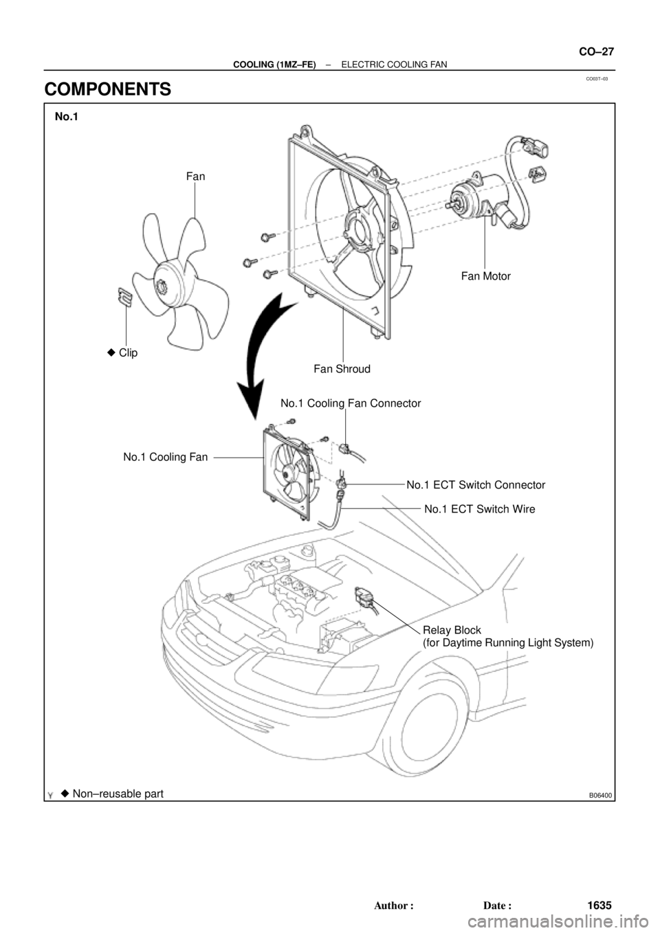
B06400
No.1 Cooling FanNo.1 Cooling Fan Connector
No.1 ECT Switch Connector
No.1 ECT Switch Wire
Relay Block
(for Daytime Running Light System)
� Non±reusable part� ClipFan
Fan ShroudFan Motor
No.1
± COOLING (1MZ±FE)ELECTRIC COOLING FAN
CO±27
1635 Author�: Date�:
COMPONENTS
Page 1203 of 4592
CO03U±03
B05943
B05944
± COOLING (1MZ±FE)ELECTRIC COOLING FAN
CO±29
1637 Author�: Date�:
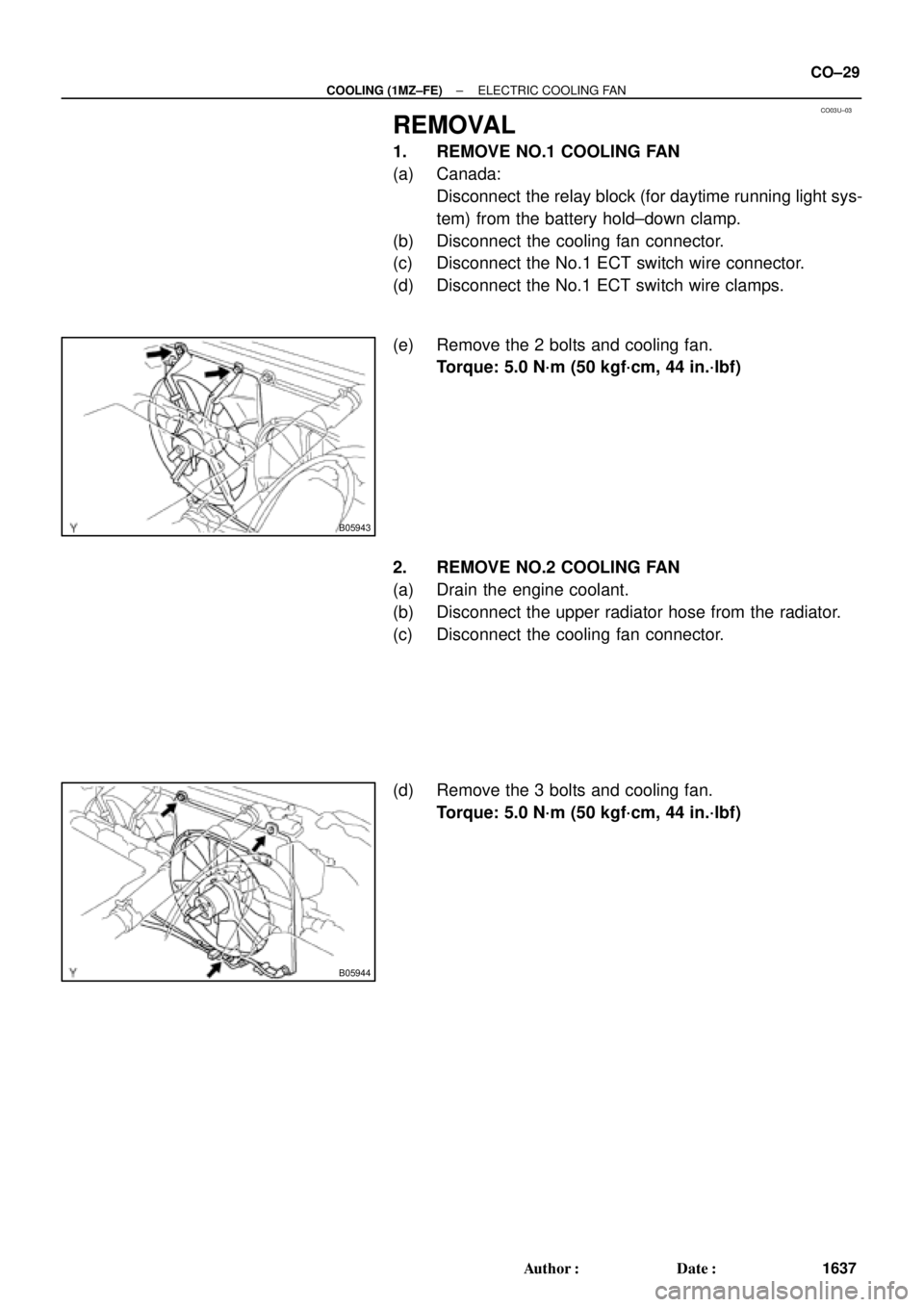
REMOVAL
1. REMOVE NO.1 COOLING FAN
(a) Canada:
Disconnect the relay block (for daytime running light sys-
tem) from the battery hold±down clamp.
(b) Disconnect the cooling fan connector.
(c) Disconnect the No.1 ECT switch wire connector.
(d) Disconnect the No.1 ECT switch wire clamps.
(e) Remove the 2 bolts and cooling fan.
Torque: 5.0 N´m (50 kgf´cm, 44 in.´lbf)
2. REMOVE NO.2 COOLING FAN
(a) Drain the engine coolant.
(b) Disconnect the upper radiator hose from the radiator.
(c) Disconnect the cooling fan connector.
(d) Remove the 3 bolts and cooling fan.
Torque: 5.0 N´m (50 kgf´cm, 44 in.´lbf)
Page 1214 of 4592

DI00G±05
ENGINE CONTROL SYSTEM Check Sheet
Customer's Name
Driver's Name
Data Vehicle
Brought in
License No.
Model and Model
Year
Frame No.
Engine Model
Odometer Reading
Problem Symptoms
Engine does
not Start
Difficult to
Start
Poor Idling
Poor
Driveaability
Engine Stall
Others
Engine does not crankNo initial combustionNo complete combustion
Engine cranks slowly
Other
Incorrect first idleIdling rpm is abnormalHigh ( rpm)Low ( rpm)
Rough idling
Other
HesitationBack fireMuffler explosion (after±fire)Surging
Knocking
Other
Soon after startingAfter accelerator pedal depressed
After accelerator pedal released
During A/C operation
Shifting from N to D
Other
Datas Problem
Occurred
Problem Frequency
Condition When
Problem Occurs
Weather
Engine Operation
Engine Temperature Place Outdoor
TemperatureConstant
Sometimes ( times per day/month)Once only
Other
Fine
CloudyRainySnowyVarious/Other
Hot
Warm CoolCold (approx. °F/ °C)
Highway
SuburbsInner cityUphillDownhill
Rough road
Other
Cold
Warming upAfter warming upAny temperatureOther
Starting
Just after starting ( min.)IdlingRacing
Driving
Constant speedAccelerationDeceleration
A/C switch ON/OFF
Other
Condition of MILRemains on Sometimes light up Does not light up
NormalMalfunction code(s) (code )
Freezed frame data ( )
NormalMalfunction code(s) (code )
Freezed frame data ( )
Normal Mode
(Precheck)
Check Mode DTC InspectionInspector's
Name
km
miles
DI±2
± DIAGNOSTICSENGINE (5S±FE)
237 Author�: Date�:
CUSTOMER PROBLEM ANALYSIS CHECK