Page 1301 of 4592

DI±89
324 Author�: Date�:
DTC P0300 Random/Multiple Cylinder Misfire Detected
DTC P0301 Cylinder 1 Misfire Detected
DTC P0302 Cylinder 2 Misfire Detected
DTC P0303 Cylin")
± DIAGNOSTICSENGINE (5S±FE)
DI±89
324 Author�: Date�:
DTC P0300 Random/Multiple Cylinder Misfire Detected
DTC P0301 Cylinder 1 Misfire Detected
DTC P0302 Cylinder 2 Misfire Detected
DTC P0303 Cylinder 3 Misfire Detected
DTC P0304 Cylinder 4 Misfire Detected
CIRCUIT DESCRIPTION
Misfire: The ECM uses the crankshaft position sensor and camshaft position sensor to monitor changes in
the crankshaft rotation for each cylinder.
The ECM counts the number of times the engine speed change rate indicates that misfire has occurred. And
when the misfire rate equals or exceeds the count indicating that the engine condition has deteriorated, the
MIL lights up.
If the misfire rate is high enough and the driving conditions will cause catalyst overheating, the MIL blinks
when misfiring occurs.
DTC No.DTC Detecting ConditionTrouble Area
P0300Mi fi i f d li d i d t t d d i ti l
�Ignition system
�Injector
�Fuel line pressure
�EGR
P0300
P0301
P0302
P0303
P0304
Misfiring of random cylinders is detected during any particular
200 or 1,000 revolutions
For any particular 200 revolutions for engine, misfiring is de-
tected which can cause catalyst overheating
(This causes MIL to blink)
�EGR
�Compression pressure
�Valve clearance not to specification
�Valve timing
�Manifold absolute pressure sensor
P0304(This causes MIL to blink)�Manifold absolute ressure sensor
�Engine coolant temp. sensor
�Open or short in engine wire
�Connector connection
�ECM
HINT:
When the 2 or more codes for a misfiring cylinder are recorded repeatedly but no random misfire code is
recorded, it indicates that the misfires were detected and recorded at different times.
DI011±07
Page 1317 of 4592

DI±105
340 Author�: Date�:
DTC P0401 Exhaust Gas Recirculation Flow Insufficient")
P25430
ECM
Throttle Body
EGR
Vacuum
Modulator EGR Valve
VSV
Exhaust Gas Throttle
Valve
u
± DIAGNOSTICSENGINE (5S±FE)
DI±105
340 Author�: Date�:
DTC P0401 Exhaust Gas Recirculation Flow Insufficient
Detected
CIRCUIT DESCRIPTION
The EGR system recirculates exhaust gas, which is controlled to the proper quantity to suit the driving condi-
tions, into the intake air mixture to slow down combustion, reduce the combustion temperature and reduce
NOx emissions. The amount of EGR is regulated by the EGR vacuum modulator according to the engine
load.
If even one of the following conditions is fulfilled, the VSV is
turned ON by a signal from the ECM.
This results in atmospheric air acting on the EGR valve, closing
the EGR valve and shutting off the exhaust gas (EGR cut±off).
Under the following conditions, EGR is cut to maintain driveabil-
ity.
�Before engine is warmed up.
�During deceleration (throttle valve closed).
�Light engine load (amount of intake air very small).
�Engine idling.
�Engine speed over 4,400 rpm.
�High engine load (amount of intake air very large).
DTC No.DTC Detecting ConditionTrouble Area
P0401
After engine is warmed up, intake manifold absolute pressure
is larger than value calculated by ECM while EGR system is
ON
(2 trip detection logic)
�EGR valve stuck closed
�Open or short in VSV circuit for EGR
�Vacuum or EGR hose disconnected
�Manifold absolute pressure sensor
�VSV for EGR open or close malfunction
�ECM
DI015±05
Page 1319 of 4592

Idling
IG SW OFF
(1)(2)
Warm up
3 ~ 5 min.2 min.
3 ~ 5 min.Time (3)
(4)
(5)(6)
(7)
2 min.
± DIAGNOSTICSENGINE (5S±FE)
DI±107
342 Author�: Date�:
SYST")
P20769
Vehicle Speed
60 ~ 80 km/h
(38 ~ 50 mph)
Idling
IG SW OFF
(1)(2)
Warm up
3 ~ 5 min.2 min.
3 ~ 5 min.Time (3)
(4)
(5)(6)
(7)
2 min.
± DIAGNOSTICSENGINE (5S±FE)
DI±107
342 Author�: Date�:
SYSTEM CHECK DRIVING PATTERN
(1) Connect the OBD II scan tool or TOYOTA hand±held tester to the DLC3.
(2) Start and warm up the engine with all accessories switched OFF.
(3) Run the vehicle at 60 ~ 80 km/h (38 ~ 50 mph) for 3 min. or more.
(4) Idle the engine for about 2 min.
(5) Do steps (3) and (4) again.
(6) Stop at safe place and turn the ignition switch OFF.
(7) Do steps (2) to (5) again.
(8) Check the READINESS TESTS mode on the OBD II scan tool or TOYOTA hand±held tester.
If COMPL is displayed and the MIL does not light up, the system is normal.
If INCMPL is displayed and the MIL does not light up, run the vehicle again and check it.
HINT:
INCMPL is displayed when either condition (a) or (b) exists.
(a) The system check is incomplete.
(b) There is a malfunction in the system.
If there is a malfunction in the system, the MIL will light up after steps (2) to (5) above are done.
(2 trip detection logic)
INSPECTION PROCEDURE
HINT:
�If DTC P0105 (Manifold Absolute Pressure/Barometric Pressure Circuit Malfunction), P0106 (Manifold
Absolute Pressure/Barometric Pressure Circuit Range/Performance Problem) and P0401 (Exhaust
Gas Recirculation Flow Insufficient Detected) are output simultaneously, perform troubleshooting of
DTC P0105 first.
�If DTC P0401 (Exhaust Gas Recirculation Flow Insufficient Detected) and P0402 (Exhaust Gas Recir-
culation Flow Excessive Detected) are output simultaneously, perform troubleshooting of DTC P0402
first.
�Read freeze frame data using TOYOTA hand±held tester or OBD II scan tool. Because freeze frame
records the engine conditions when the malfunction is detected, when troubleshooting it is useful for
determining whether the vehicle was running or stopped, the engine warmed up or not, the air±fuel
ratio lean or rich, etc. at the time of the malfunction.
Page 1329 of 4592
(c)
(d)
(b)
FI6514
OX Signal Waveform (Oscilloscope)
1.0 V
0 V
200 msec. /Division
± DIAGNOSTICSENGINE (5S±F")
FI7132
Engine Speed
2,500 ~ 3,000 rpm
Idling
IG SW OFF
Warmed up3 min. or soCheck
Time (a)(c)
(d)
(b)
FI6514
OX Signal Waveform (Oscilloscope)
1.0 V
0 V
200 msec. /Division
± DIAGNOSTICSENGINE (5S±FE)
DI±117
352 Author�: Date�:
CONFIRMATION ENGINE RACING PATTERN
(a) Connect the TOYOTA hand±held tester to the DLC3, or connect the probe of the oscilloscope between
terminals OX1, OX2 and E1 of the ECM connector.
(b) Start engine and warm it up with all accessories switched OFF until water temp. is stable.
(c) Race the engine at 2,500 ~ 3,000 rpm for about 3 min.
(d) After confirming that the waveforms of the heated oxygen sensor (bank 1 sensor 1 (OX1)), oscillate
around 0.5 V during feedback to the ECM, check the waveform of the heated oxygen sensor (bank
1 sensor 2 (OX2)).
HINT:
�If there is a malfunction in the system, the waveform of the
heated oxygen sensor (bank 1 sensor 2 (OX2)) is almost
the same as that of the heated oxygen sensor (bank 1
sensor 1 (OX1)) on the left.
�There are some cases where, even though a malfunction
exists, the MIL may either light up or not light up.
Page 1365 of 4592

Idling
IG SW OFF
3 ~ 5 min.
Time
(1)(2)(4)
(3)
± DIAGNOSTICSENGINE (5S±FE)
DI±153
388 Author�: Date�:
CONFIRMATION DRIVING PATTERN
(1) Connect the")
A00364
Vehicle Speed
60 ~ 120 km/h
(38 ~ 75 mph)
Idling
IG SW OFF
3 ~ 5 min.
Time
(1)(2)(4)
(3)
± DIAGNOSTICSENGINE (5S±FE)
DI±153
388 Author�: Date�:
CONFIRMATION DRIVING PATTERN
(1) Connect the TOYOTA hand±held tester to the DLC3.
(2) Switch the TOYOTA hand±held tester from normal mode to check mode (See page DI±3).
(3) Start the engine and warm it up with all accessory switches OFF.
(4) Drive the vehicle at 60 ~ 120 km/h (38 ~ 75 mph) and engine speed at 1,600 ~ 3,200 rpm for 3
~ 5 min.
HINT:
If a malfunction exists, the MIL will light up during step (4).
NOTICE:
If the conditions in this test are not strictly followed, detection of the malfunction will not be possible.
If you do not have a TOYOTA hand±held tester, turn the ignition switch OFF after performing steps
(3) and (4), then perform steps (3) and (4) again.
INSPECTION PROCEDURE
HINT:
Read freeze frame data using TOYOTA hand±held tester or OBD II scan tool. Because freeze frame records
the engine conditions when the malfunction is detected, when troubleshooting it is useful for determining
whether the vehicle was running or stopped, the engine warmed up or not, the air±fuel ratio lean or rich, etc.
at the time of the malfunction.
1 Are there any other codes (besides DTC P1130) being output?
YES Go to relevant DTC chart.
NO
Page 1382 of 4592
 Stop
Light
(RH) G±R
2
52
5
W±B
W±B
BP High
Mount
Stop
Light
2
1R
A
A")
A03604
ECM
STP 4
E7
G±W G±WJ27 J28 1R 1R
1SJ27
J/C
AC Instrument Panel J/B
5
2 4
7
12
G±WLight
Failure
Sensor
Stop
Light
(LH) Stop
Light
(RH) G±R
2
52
5
W±B
W±B
BP High
Mount
Stop
Light
2
1R
A
A
J40
J/C
BL
1
W±B
Stop Light
Switch
2
BatteryW±B W
1C 7
STOP
41BInstrument
Panel J/B
B±R
B±R
F9 2 F9 1
ALT
F4MAIN
FL
FL Block
G±W
1
*1: w/o Immobiliser
*2: w/ Immobiliser(*1) (*2)
E79 DI±170
± DIAGNOSTICSENGINE (5S±FE)
405 Author�: Date�:
DTC P1520 Stop Light Switch Signal Malfunction (Only
for A/T)
CIRCUIT DESCRIPTION
This signal is used to detect when the brakes have been applied. The STP signal voltage is the same as
the voltage supplied to the stop lights.
The STP signal is used mainly to control the fuel cut±off engine speed. (The fuel cut±off engine speed is
reduced slightly when the vehicle is braking.)
DTC No.DTC Detecting ConditionTrouble Area
P1520Stop light switch does not turn off even once vehicle is driven
(2 trip detection logic)�Short in stop light switch signal circuit
�Stop light switch
�ECM
WIRING DIAGRAM
DI01H±07
Page 1383 of 4592
± DIAGNOSTICSENGINE (5S±FE)
DI±171
406 Author�: Date�:
INSPECTION PROCEDURE
HINT:
Read freeze frame data using TOYOTA hand±held tester or OBD II scan tool. Because freeze frame records
the engine conditions when the malfunction is detected, when troubleshooting it is useful for determining
whether the vehicle was running or stopped, the engine warmed up or not, the air±fuel ratio lean or rich, etc.
at the time of the malfunction.
1 Check operation of stop light.
PREPARATION:
Check if the stop lights go on and off normally when the brake pedal is operated and released.
NG Check and repair stop light circuit
(See page BE±37).
OK
Page 1384 of 4592
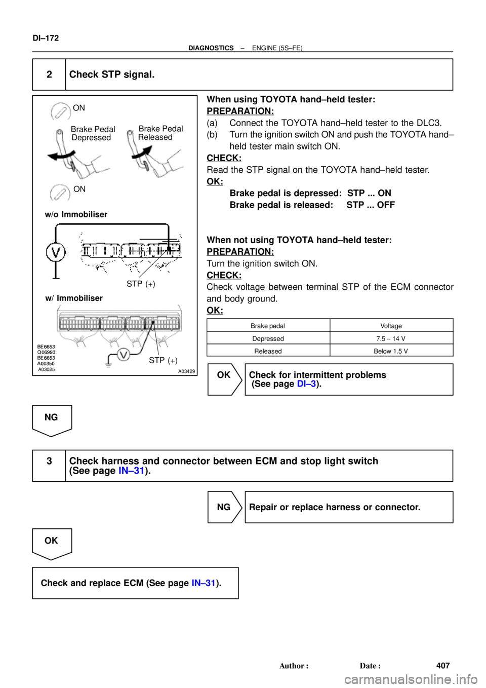
A03025A03429
Brake Pedal
Depressed
ON ON
STP (+) Brake Pedal
Released
w/o Immobiliser
w/ Immobiliser
STP (+)
DI±172
± DIAGNOSTICSENGINE (5S±FE)
407 Author�: Date�:
2 Check STP signal.
When using TOYOTA hand±held tester:
PREPARATION:
(a) Connect the TOYOTA hand±held tester to the DLC3.
(b) Turn the ignition switch ON and push the TOYOTA hand±
held tester main switch ON.
CHECK:
Read the STP signal on the TOYOTA hand±held tester.
OK:
Brake pedal is depressed: STP ... ON
Brake pedal is released: STP ... OFF
When not using TOYOTA hand±held tester:
PREPARATION:
Turn the ignition switch ON.
CHECK:
Check voltage between terminal STP of the ECM connector
and body ground.
OK:
Brake pedalVoltage
Depressed7.5 ~ 14 V
ReleasedBelow 1.5 V
OK Check for intermittent problems
(See page DI±3).
NG
3 Check harness and connector between ECM and stop light switch
(See page IN±31).
NG Repair or replace harness or connector.
OK
Check and replace ECM (See page IN±31).