Page 1090 of 4592
P14433
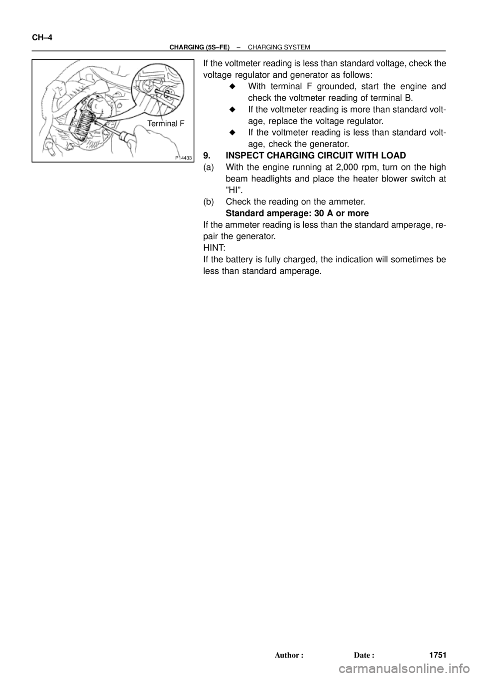
Terminal F CH±4
± CHARGING (5S±FE)CHARGING SYSTEM
1751 Author�: Date�:
If the voltmeter reading is less than standard voltage, check the
voltage regulator and generator as follows:
�With terminal F grounded, start the engine and
check the voltmeter reading of terminal B.
�If the voltmeter reading is more than standard volt-
age, replace the voltage regulator.
�If the voltmeter reading is less than standard volt-
age, check the generator.
9. INSPECT CHARGING CIRCUIT WITH LOAD
(a) With the engine running at 2,000 rpm, turn on the high
beam headlights and place the heater blower switch at
ºHIº.
(b) Check the reading on the ammeter.
Standard amperage: 30 A or more
If the ammeter reading is less than the standard amperage, re-
pair the generator.
HINT:
If the battery is fully charged, the indication will sometimes be
less than standard amperage.
Page 1103 of 4592
CHARGING SYSTEM
CH±1
1764 Author�: Date�:
CHARGING SYSTEM
ON±VEHICLE INSPECTION
CAUTI")
CH01D±01
Z11577
Except Maintenance±Free Battery
Z11556
Maintenance±Free BatteryVoltmeter
± CHARGING (1MZ±FE)CHARGING SYSTEM
CH±1
1764 Author�: Date�:
CHARGING SYSTEM
ON±VEHICLE INSPECTION
CAUTION:
�Check that the battery cables are connected to the
correct terminals.
�Disconnect the battery cables when the battery is
given a quick charge.
�Do not perform tests with a high voltage insulation
resistance tester.
�Never disconnect the battery while the engine is
running.
1. CHECK BATTERY ELECTROLYTE LEVEL
Check the electrolyte quantity of each cell.
(1) Maintenance±Free Battery:
If under the lower level, replace the battery (or add
distilled water if possible). Check the charging sys-
tem.
(2) Except Maintenance±Free Battery:
If under the lower level, add distilled water.
2. Except Maintenance±Free Battery:
CHECK BATTERY SPECIFIC GRAVITY
Check the specific gravity of each cell.
Standard specific gravity: 1.25 ± 1.29 at 20°C (68°F)
If the specific gravity is less than specification, charge the bat-
tery.
3. Maintenance±Free Battery:
CHECK BATTERY VOLTAGE
(a) After having driven the vehicle and in the case that 20
minutes have not passed after having stopped the en-
gine, turn the ignition switch ON and turn on the electrical
system (headlight, blower motor, rear defogger etc.) for
60 seconds to remove the surface charge.
(b) Turn the ignition switch OFF and turn off the electrical sys-
tems.
(c) Measure the battery voltage between the negative (±)
and positive (+) terminals of the battery.
Standard voltage: 12.5 ± 12.9 V at 20°C (68°F)
If the voltage is less than specification, charge the battery.
Page 1104 of 4592

Z18811
Maintenance±Free Battery
Type A
Type B
Blue White Red
OK Charging
NecessaryInsufficient
Water
GREEN EYE DARK EYECLEAR EYE or
CHARGED DISCHARGED ADD WATERLIGHT YELLOW
Z00015
Z00038
DENSO
Borroughs
CH0086
CORRECT WRONG CH±2
± CHARGING (1MZ±FE)CHARGING SYSTEM
1765 Author�: Date�:
HINT:
Check the indicator as shown in the illustration.
4. CHECK BATTERY TERMINALS, FUSIBLE LINK AND
FUSES
(a) Check that the battery terminals are not loose or cor-
roded.
If the terminals are corroded, clean the terminals.
(b) Check the fusible link, H±fuses, M±fuse and fuses for
continuity.
5. INSPECT DRIVE BELTS
(a) Visually check the drive belt for excessive wear, frayed
cords etc.
If any defect has been found, replace the drive belt.
HINT:
Cracks on the rib side of a drive belt are considered acceptable.
If the drive belt has chunks missing from the ribs, it should be
replaced.
(b) Using a belt tension gauge, measure the belt tension.
Belt tension gauge:
DENSO BTG±20 (95506±00020)
Borroughs No. BT±33±73F
Drive belt tension:
New belt175 ± 5 lbf
Used belt115 ± 20 lbf
If the belt tension is not as specified, adjust it.
HINT:
�ºNew beltº refers to a belt which has been used less than
5 minutes on a running engine.
�ºUsed beltº refers to a belt which has been used on a run-
ning engine for 5 minutes or more.
�After installing a belt, check that it fits properly in the
ribbed grooves.
�Check with your hand to confirm that the belt has not
slipped out of the groove on the bottom of the pulley.
Page 1105 of 4592
CHARGING SYSTEM
CH±3
1766 Author�: Date�: �
After installing a new belt, run the engine for about 5 min-")
Z03473
BatteryAmmeter
VoltmeterDisconnect Wire
from Terminal B
Generator
± CHARGING (1MZ±FE)CHARGING SYSTEM
CH±3
1766 Author�: Date�: �
After installing a new belt, run the engine for about 5 min-
utes and recheck the belt tension.
6. VISUALLY CHECK GENERATOR WIRING AND
LISTEN FOR ABNORMAL NOISES
(a) Check that the wiring is in good condition.
(b) Check that there is no abnormal noise from the generator
while the engine is running.
7. CHECK DISCHARGE WARNING LIGHT CIRCUIT
(a) Warm up the engine and then turn it off.
(b) Turn off all accessories.
(c) Turn the ignition switch ºONº. Check that the discharge
warning light is lit.
(d) Start the engine. Check that the light goes off.
If the light does not go off as specified, troubleshoot the dis-
charge light circuit.
8. INSPECT CHARGING CIRCUIT WITHOUT LOAD
HINT:
If a battery/generator tester is available, connect the tester to
the charging circuit as per manufacturer's instructions.
(a) If a tester is not available, connect a voltmeter and amme-
ter to the charging circuit as follows:
�Disconnect the wire from terminal B of the genera-
tor, and connect it to the negative (±) tester probe
of the ammeter.
�Connect the positive (+) tester probe of the amme-
ter to terminal B of the generator.
�Connect the positive (+) tester probe of the voltme-
ter to terminal B of the generator.
�Ground the negative (±) tester probe of the voltme-
ter.
(b) Check the charging circuit as follows:
With the engine running from idling to 2,000 rpm, check
the reading on the ammeter and voltmeter.
Standard amperage: 10 A or less
Standard voltage: 13.5 ± 15.1 V
If the voltmeter reading is more than standard voltage, replace
the voltage regulator.
Page 1106 of 4592
P14228
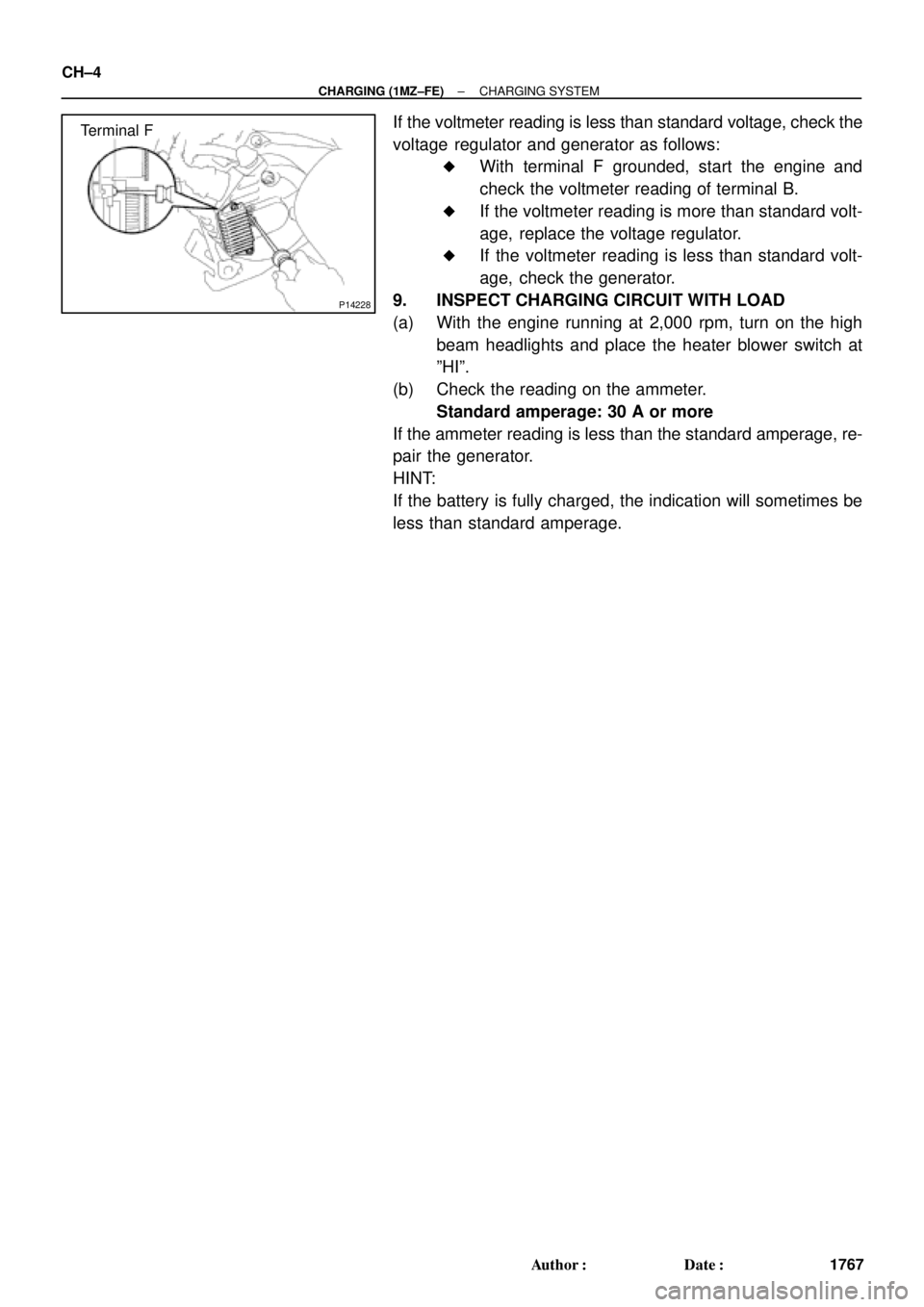
Terminal F CH±4
± CHARGING (1MZ±FE)CHARGING SYSTEM
1767 Author�: Date�:
If the voltmeter reading is less than standard voltage, check the
voltage regulator and generator as follows:
�With terminal F grounded, start the engine and
check the voltmeter reading of terminal B.
�If the voltmeter reading is more than standard volt-
age, replace the voltage regulator.
�If the voltmeter reading is less than standard volt-
age, check the generator.
9. INSPECT CHARGING CIRCUIT WITH LOAD
(a) With the engine running at 2,000 rpm, turn on the high
beam headlights and place the heater blower switch at
ºHIº.
(b) Check the reading on the ammeter.
Standard amperage: 30 A or more
If the ammeter reading is less than the standard amperage, re-
pair the generator.
HINT:
If the battery is fully charged, the indication will sometimes be
less than standard amperage.
Page 1159 of 4592
RADIATOR
CO±19
1593 Author�: Date�:
DISASSE")
CO06K±03
CO1205
Dimension ºBº
Overhaul HandleStopper Bolt SSTPart ºAº
Claw
S04699
Stopper
BoltSSTTank
Lock
Plate
S04703
Ta p
S04705
± COOLING (5S±FE)RADIATOR
CO±19
1593 Author�: Date�:
DISASSEMBLY
1. REMOVE ECT SWITCH
(a) Remove the ECT switch.
(b) Remove the O±ring.
2. REMOVE DRAIN PLUG
(a) Remove the drain plug.
(b) Remove the O±ring.
3. ASSEMBLE SST
SST 09230±01010
(a) Install the claw to the overhaul handle, inserting it in the
hole in part ºAº as shown in the diagram.
(b) While gripping the handle, adjust the stopper bolt so that
dimension ºBº is as shown in the illustration.
Dimension: 0.2 ± 0.3 mm (0.008 ± 0.012 in)
NOTICE:
If this adjustment is not done the claw may be damaged.
4. UNCAULK LOCK PLATES
Using SST to release the caulking, squeeze the handle until
stopped by the stopper bolt.
SST 09230±01010
5. REMOVE TANKS AND O±RINGS
Lightly tap the bracket of the radiator (or radiator inlet or outlet)
with a soft±faced hammer, and remove the tank and the O±ring.
6. A/T:
REMOVE OIL COOLER FROM LOWER TANK
(a) Loosen the nut, and remove the cooler pipe.
(b) Remove the 2 nuts and plate washers.
(c) Remove the oil cooler and 2 O±rings.
Page 1160 of 4592
RADIATOR
1594 Author�:")
CO06L±04
S05307
DownwardPipe
18°
CO1267
Lock Plate
CoreLock Plate
CO0317
� Normal
O±RingX Twisted
X Twisted
S04698
Ta pWRONG
CORRECT
Tank
Lock
Plate CO±20
± COOLING (5S±FE)RADIATOR
1594 Author�: Date�:
REASSEMBLY
1. A/T:
INSTALL OIL COOLER TO LOWER TANK
(a) Install 2 new O±rings to the oil cooler.
(b) Install the oil cooler to the lower tank with the 2 plate
washers and nuts.
Torque: 8.3 N´m (85 kgf´cm, 74 in.´lbf)
(c) Install the cooler pipe in the direction indicated in the il-
lustration.
Torque: 14.7 N´m (150 kgf´cm, 11 ft´lbf)
2. INSPECT LOCK PLATE FOR DAMAGE
HINT:
�If the sides of the lock plate groove are deformed, reas-
sembly of the tank will be impossible.
�Therefore, first correct any deformation with pliers or simi-
lar object. Water leakage will result if the bottom of the
lock plate groove is damaged or dented.
NOTICE:
The radiator can only be recaulked 2 times. After the 2nd
time, the radiator core must be replaced.
3. INSTALL NEW O±RINGS AND TANKS
(a) After checking that there are no foreign objects in the lock
plate groove, install the new O±ring without twisting it.
HINT:
When cleaning the lock plate groove, lightly rub it with sand pa-
per without scratching it.
(b) Install the tank without damaging the O±ring.
(c) Tap the lock plate with a soft±faced hammer so that there
is no gap between it and the tank.
Page 1161 of 4592

(3)(3)(3)
(1) (2)
(2)
(2)
(2)
(2) (2) (2)
Z18946
± CO")
CO1206
Dimension ºBº
Stopper Bolt
Overhaul Handle Punch AssemblyPart ºAº
SST
Z18947
5
SST
Stopper
Tank
Lock 1
64
82 7
3
Plate
Bolt
S05241
(1)
(3)(3)(3)
(1) (2)
(2)
(2)
(2)
(2) (2) (2)
Z18946
± COOLING (5S±FE)RADIATOR
CO±21
1595 Author�: Date�:
4. ASSEMBLE SST
SST 09230±01010, 09231±14010
(a) Install the punch assembly to the overhaul handle, insert-
ing it in the hole in part ºAº as shown in the illustration.
(b) While gripping the handle, adjust the stopper bolt so that
dimension ºBº is as shown in the illustration.
Dimension: 8.4 mm (0.331 in)
5. CAULK LOCK PLATE
(a) Lightly press SST against the lock plate in the order
shown in the illustration. After repeating this a few times,
fully caulk the lock plate by squeezing the handle until
stopped by the stopper plate.
SST 09230±01010
HINT:
�Do not stake the areas protruding around the pipes,
brackets or tank ribs.
�The points shown in the illustration and oil cooler near
here (A/T) cannot be staked with the SST. Use pliers or
similar object and be careful not to damage the core
plates.