Page 1019 of 4592

R00954
Stop Light
Switch
Push Rod
Pedal HeightBR0YH±01
R00935
Pedal Freeplay
± BRAKEBRAKE PEDAL
BR±5
2028 Author�: Date�:
BRAKE PEDAL
ON±VEHICLE INSPECTION
1. CHECK PEDAL HEIGHT
Pedal height from asphalt sheet:
152.0 ± 162.0 mm (5.984 ± 6.378 in.)
2. IF NECESSARY, ADJUST PEDAL HEIGHT
(a) Disconnect the connector from the stop light switch.
(b) Loosen the stop light switch lock nut and remove the stop
light switch.
(c) Loosen the push rod lock nut.
(d) Adjust the pedal height by turning the pedal push rod.
(e) Tighten the push rod lock nut.
Torque: 25 N´m (260 kgf´cm, 19 ft´lbf)
(f) Install the stop light switch and turn it until it lightly con-
tacts the pedal stopper.
(g) Push in the brake pedal 5±15 mm (0.20±0.59 in.), turn the
stop light switch to lock the nut in the position where the
stop light goes off.
(h) Connect the connector to the stop light switch.
(i) After installation, push in the brake pedal 5±15 mm
(0.20±0.59 in.), check that stop light lights up.
(j) Connect the connector to the stop light switch.
(k) After adjusting the pedal height, check the pedal freeplay.
3. CHECK PEDAL FREEPLAY
(a) Stop the engine and depress the brake pedal several
times until there is no more vacuum left in the booster.
(b) Push in the pedal by hand until the resistance begins to
be felt, then measure the distance.
Pedal freeplay: 1 ± 6 mm (0.04 ± 0.24 in.)
HINT:
The freeplay to the 1st resistance is due to the play between the
clevis and pin. This is magnified up to 1 ± 6 mm (0.04 ± 0.24 in.)
at the pedal.
If incorrect, check the stop light switch clearance.
If the clearance is OK, then troubleshoot the brake system.
Stop light switch clearance:
0.5 ± 2.4 mm (0.020 ± 0.094 in.)
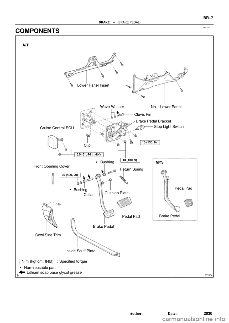
Page 1021 of 4592
BR0YI±01
F07004
Lower Panel Insert
� Bushing ClipClevis PinNo.1 Lower Panel
Return Spring
Cushion Plate
Collar
Brake Pedal
Cowl Side Trim Front Opening Cover
Brake Pedal
Inside Scuff PlateM/T: Stop Light Switch
Wave Washer
Cruise Control ECU
Lithium soap base glycol grease
13 (130, 9)
5.0 (51, 44 in.´lbf)
13 (130, 9)
Pedal Pad
Pedal Pad� Bushing A/T:
39 (400, 29)
: Specified torqueN´m (kgf´cm, ft´lbf)
� Non±reusable partBrake Pedal Bracket
± BRAKEBRAKE PEDAL
BR±7
2030 Author�: Date�:
COMPONENTS
Page 1026 of 4592
 Remove the set screw and pull out the reservoir.
Torq")
BR0AG±02
R11406
Soft Jows
R11407
Soft Jows
R12236
A BR±12
± BRAKEBRAKE MASTER CYLINDER
2035 Author�: Date�:
DISASSEMBLY
1. REMOVE RESERVOIR
(a) Remove the set screw and pull out the reservoir.
Torque: 1.7 N´m (18 kgf´cm, 16 in.´lbf)
(b) Remove the cap and strainer from the reservoir.
2. REMOVE 2 GROMMETS
3. Except w/ TRAC:
PLACE CYLINDER IN VISE
4. w/o TRAC:
REMOVE PISTON STOPPER BOLT
Using a screwdriver, push the pistons in all the way and remove
the piston stopper bolt and gasket.
HINT:
Tape the screwdriver tip before use.
Torque: 10 N´m (100 kgf´cm, 7 ft´lbf)
5. w/o TRAC:
REMOVE 2 PISTONS AND SPRINGS
(a) Push in the piston with a screwdriver and remove the
snap ring with snap ring pliers.
HINT:
Tape the screwdriver tip before use.
(b) Remove the No. 1 piston and spring by hand, pulling
straight out, not at an angle.
NOTICE:
�If pulled out and installed at an angle, there is a possi-
bility that the cylinder bore could be damaged.
�At the time of reassembly, please refer to the follow-
ing item.
Be careful not to damage the rubber lips on the pis-
tons.
(c) Place a rag and 2 wooden blocks on the work table, and
lightly tap the cylinder flange against the block edges until
the No. 2 piston drops out of the cylinder.
HINT:
Make sure that the distance (A) from the rag to the top of the
blocks is at least 100 mm (3.94 in.).
Page 1031 of 4592
BR2237
BR0AK±03
BR2238
1st3rd
2nd
GOOD
NO GOOD
± BRAKEBRAKE BOOSTER ASSEMBLY
BR±17
2040 Author�: Date�:
BRAKE BOOSTER ASSEMBLY
ON±VEHICLE INSPECTION
1. OPERATING CHECK
(a) Depress the brake pedal several times with the engine off
and check that there is no change in the pedal reserve
distance.
(b) Depress the brake pedal and start the engine. If the pedal
goes down slightly, operation is normal.
2. AIR TIGHTNESS CHECK
(a) Start the engine and stop it after 1 or 2 minutes. Depress
the brake pedal several times slowly.
If the pedal goes down farthest the 1st time, but gradually rises
after the 2nd or 3rd time, the booster is air tight.
(b) Depress the brake pedal while the engine is running, and
stop the engine with the pedal depressed. If there is no
change in the pedal reserve travel after holding the pedal
for 30 seconds, the booster is air tight.
Page 1034 of 4592
 Install the booster and a new gasket.
(b) Install the clevis")
BR0AN±03
F03521
SST
Gasket
R11347
SST BR±20
± BRAKEBRAKE BOOSTER ASSEMBLY
2043 Author�: Date�:
INSTALLATION
1. INSTALL BRAKE BOOSTER
(a) Install the booster and a new gasket.
(b) Install the clevis to the operating rod.
(c) Install and torque the booster installation nuts.
Torque: 13 N´m (130 kgf´cm, 9 ft´lbf)
(d) Install the clevis, and torque the lock nut.
Torque: 25 N´m (260 kgf´cm, 19 ft´lbf)
(e) Install the clevis pin into the clevis and brake pedal, and
install the clip to the clevis pin.
(f) Install the pedal return spring.
2. ADJUST LENGTH OF BOOSTER PUSH ROD
(a) Install a new gasket on the master cylinder.
(b) Set the SST on the gasket, and lower the pin until its tip
slightly touches the piston.
SST 09737±00010
(c) Turn the SST upside down, and set it on the booster.
SST 09737±00010
(d) Measure the clearance between the booster push rod
and pin head (SST).
Clearance: 0 mm (0 in.)
(e) Adjust the booster push rod length until the push rod light-
ly touches the pin head.
3. INSTALL CHARCOAL CANISTER TO ORIGINAL POSI-
TION
4. INSTALL MASTER CYLINDER (See page BR±16)
5. INSTALL AIR CLEANER COVER WITH AIR CLEANER
HOSE
6. CONNECT VACUUM HOSE TO BRAKE BOOSTER
7. FILL BRAKE RESERVOIR WITH BRAKE FLUID AND
BLEED BRAKE SYSTEM (See page BR±4)
8. CHECK FOR FLUID LEAKAGE
9. CHECK AND ADJUST BRAKE PEDAL
(See page BR±5)
10. DO OPERATIONAL CHECK (See page BR±17)
Page 1087 of 4592
CHARGING SYSTEM
CH±1
1748 Author�: Date�:
CHARGING SYSTEM
ON±VEHICLE INSPECTION
CAUTI")
CH02U±01
Z11577
Except Maintenance±Free Battery
Z11556
Maintenance±Free Battery
Voltmeter
± CHARGING (5S±FE)CHARGING SYSTEM
CH±1
1748 Author�: Date�:
CHARGING SYSTEM
ON±VEHICLE INSPECTION
CAUTION:
�Check that the battery cables are connected to the
correct terminals.
�Disconnect the battery cables when the battery is giv-
en a quick charge.
�Do not perform tests with a high voltage insulation re-
sistance tester.
�Never disconnect the battery while the engine is run-
ning.
1. CHECK BATTERY ELECTROLYTE LEVEL
Check the electrolyte quantity of each cell.
Maintenance±Free Battery:
If under the lower level, replace the battery (or add distilled wa-
ter if possible). Check the charging system.
Except Maintenance±Free Battery:
If under the lower level, add distilled water.
2. Except Maintenance±Free Battery:
CHECK BATTERY SPECIFIC GRAVITY
Check the specific gravity of each cell.
Standard specific gravity:
1.25 ± 1.29 at 20°C (68°F)
If the specific gravity is less than specification, charge the bat-
tery.
3. Maintenance±Free Battery:
CHECK BATTERY VOLTAGE
(a) After having driven the vehicle and in the case that 20
minutes have not passed after having stopped the en-
gine, turn the ignition switch ON and turn on the electrical
system (headlight, blower motor, rear defogger etc.) for
60 seconds to remove the surface charge.
(b) Turn the ignition switch OFF and turn off the electrical sys-
tems.
(c) Measure the battery voltage between the negative (±)
and positive (+) terminals of the battery.
Standard voltage: 12.5 ± 12.9 V at 20°C (68°F)
If the voltage is less than specification, charge the battery.
Page 1088 of 4592

Z18811
Maintenance±Free Battery
Type A
Type B
Blue White Red
OK Charging
NecessaryInsufficient
Water
GREEN EYE DARK EYECLEAR EYE or
CHARGED DISCHARGED ADD WATERLIGHT YELLOW
Z00015
Z00038
DENSOBorroughs
CH0086
CORRECTWRONG CH±2
± CHARGING (5S±FE)CHARGING SYSTEM
1749 Author�: Date�:
HINT:
Check the indicator as shown in the illustration.
4. CHECK BATTERY TERMINALS, FUSIBLE LINK AND
FUSES
(a) Check that the battery terminals are not loose or cor-
roded.
If the terminals are corroded, clean the terminals.
(b) Check the fusible link, H±fuses, M±fuse and fuses for
continuity.
5. INSPECT DRIVE BELTS
(a) Visually check the drive belt for excessive wear, frayed
cords etc.
If any defect has been found, replace the drive belt.
HINT:
Cracks on the rib side of a drive belt are considered acceptable.
If the drive belt has chunks missing from the ribs, it should be
replaced.
(b) Using a belt tension gauge, measure the belt tension.
Belt tension gauge:
DENSO BTG±20 (95506±00020)
Borroughs No. BT±33±73F
Drive belt tension:
w/ A/C New belt
Used belt165 ± 25 lbf
110 ± 10 lbf
w/o A/C New belt
Used belt125 ± 25 lbf
95 ± 20 lbf
If the belt tension is not as specified, adjust it.
HINT:
�ºNew beltº refers to a belt which has been used less than
5 minutes on a running engine.
�ºUsed beltº refers to a belt which has been used on a run-
ning engine for 5 minutes or more.
�After installing a belt, check that it fits properly in the
ribbed grooves.
�Check with your hand to confirm that the belt has not
slipped out of the groove on the bottom of the pulley.
Page 1089 of 4592
CHARGING SYSTEM
CH±3
1750 Author�: Date�: �
After installing a new belt, run the engine for about 5 min")
Z03473
BatteryVoltmeter
Generator Ammeter
Disconnect Wire
from Terminal B
B
± CHARGING (5S±FE)CHARGING SYSTEM
CH±3
1750 Author�: Date�: �
After installing a new belt, run the engine for about 5 min-
utes and recheck the belt tension.
6. VISUALLY CHECK GENERATOR WIRING AND
LISTEN FOR ABNORMAL NOISES
(a) Check that the wiring is in good condition.
(b) Check that there is no abnormal noise from the generator
while the engine is running.
7. CHECK CHARGE WARNING LIGHT CIRCUIT
(a) Warm up the engine and then turn it off.
(b) Turn off all accessories.
(c) Turn the ignition switch ºONº. Check that the charge warn-
ing light is lit.
(d) Start the engine. Check that the light goes off.
If the light does not go off as specified, troubleshoot the charge
light circuit.
8. INSPECT CHARGING CIRCUIT WITHOUT LOAD
HINT:
If a battery/generator tester is available, connect the tester to
the charging circuit as per manufacturer's instructions.
(a) If a tester is not available, connect a voltmeter and amme-
ter to the charging circuit as follows:
(1) Disconnect the wire from terminal B of the genera-
tor, and connect it to the negative (±) tester probe
of the ammeter.
(2) Connect the positive (+) tester probe of the amme-
ter to terminal B of the generator.
(3) Connect the positive (+) tester probe of the voltme-
ter to terminal B of the generator.
(4) Ground the negative (±) tester probe of the voltme-
ter.
(b) Check the charging circuit as follows:
With the engine running from idling to 2,000 rpm, check
the reading on the ammeter and voltmeter.
Standard amperage: 10 A or less
Standard voltage: 13.5 ± 15.1 V
If the voltmeter reading is more than standard voltage, replace
the voltage regulator.