Page 975 of 4592
 or more BO±130
± BODYSEAT BELT PRETENSIONER
2478 Author�: Date�:
(5) Connect the 2 SST, then connect them to the seat
belt pretensioner.
SST 09082±00700, 09082±0")
H01880
SST SST
R13455
10 m (33 ft) or more BO±130
± BODYSEAT BELT PRETENSIONER
2478 Author�: Date�:
(5) Connect the 2 SST, then connect them to the seat
belt pretensioner.
SST 09082±00700, 09082±00740
NOTICE:
To avoid damaging the SST connector and wire harness,
do not lock the secondary lock of secondary lock of the
twin lock.
(6) Move the SST to at least 10mm (33 ft) from the front
of the vehicle.
(7) Close all the doors and windows of the vehicle.
NOTICE:
Take care not to damage the SST wire harness.
(8) Connect the SST red clip the battery positive (±) ter-
minal and the black clip to the negative (+) terminal.
(c) Deploy the airbag.
(1) Confirm that no one is inside the vehicle or within 10
m (33 ft) area around of the vehicle.
(2) Press the SST activation switch and activate the
seat belt pretensioner.
HINT:
The seat belt pretensioner operates simultaneously as the LED
of the SST activation switch light up.
(d) Disposal of front seat outer belt (with seat belt pretension-
er).
CAUTION:
�The front seat outer belt is very hot when the seat belt
pretensioner is deployed, so leave it alone for at least
30 minutes after deployment.
�Use gloves and safety glasses when handling a front
seat outer belt with deployed seat belt pretensioner.
�Always wash your hands with water after completing
the operation.
�Do not apply water, etc. to a front seat outer belt with
deployed seat belt pretensioner.
When scrapping a vehicle, activate the seat belt preten-
sioner and scrap the vehicle with operated front seat out-
er belt still installed.
Page 977 of 4592
 or more
H01882
BO±132
± BODYSEAT BELT PRETENSIONER
2480 Author�: Date�:
(d) Deploy the seat belt pretensioner.
(1) Connect the SST red clip to the battery positive (+)
terminal")
R05181
10 m (33 ft) or more
H01882
BO±132
± BODYSEAT BELT PRETENSIONER
2480 Author�: Date�:
(d) Deploy the seat belt pretensioner.
(1) Connect the SST red clip to the battery positive (+)
terminal and black clip to the battery negative (±)
terminal.
(2) Check that no one is within 10 m (33 ft) area around
of the disc wheel.
(3) Press the SST activation switch and activate the
seat belt pretensioner.
HINT:
The seat belt pretensioner operates simultaneously as the LED
of the SST activation switch lights up.
(e) Disposal of front seat outer belt (with seat belt pretension-
er).
CAUTION:
�The front seat outer belt is very hot when the seat belt
pretensioner is deployed, so leave it alone for at least
30 minutes after deployment.
�Use gloves and safety glasses when handling a front
seat outer belt with deployed seat belt pretensioner.
�Always wash your hands with water after completing
the operation.
�Do not apply water, etc. to a front seat outer belt with
deployed seat belt pretensioner.
(1) Remove the disc wheel and SST.
(2) Place the front seat outer belt in a vinyl bag, tie the
end tightly and dispose of in it the same way as oth-
er general parts.
Page 980 of 4592

BE16T±01
± BODY ELECTRICALTROUBLESHOOTING
BE±1
533 Author�: Date�:
TROUBLESHOOTING
PROBLEM SYMPTOMS TABLE
COMBINATION METER
METER, GAUGES AND ILLUMINATION:
SymptomSuspect AreaSee page
Tachometer, Fuel Gauge and Engine Coolant Temperature Gauge
do not operate.1. GAUGE Fuse (I/P J/B No.1)
2. Meter Circuit Plate
3. Wire Harness±
BE±4
±
Fuel Gauge does not operate or abnormal operation.
1. Fuel Receiver Gauge
2. Fuel Temperature Sensor (For Delivery Pipe)
3. Fuel Temperature Sensor (For Fuel Tank)
4. Fuel Pressure Sensor (For Delivery Pipe)
5. Fuel Pressure Sensor (For Fuel Pipe)
6. ECM
7. Meter Circuit Plate
8. Wire HarnessBE±5
SF±36
SF±40
SF±42
SF±45
±
BE±4
±
Engine Coolant Temperature Gauge does not operate or abnormal
operation
1. Engine Coolant Temperature Receiver Gauge
2. Engine Coolant Temperature Sender Gauge
3. Meter Circuit Plate
4. Wire HarnessBE±5
BE±5
BE±4
±
All illumination lights do not light up.
1. TAIL Fuse (I/P J/B No.1)
2. Light Control Rheostat
3. Wire Harness±
BE±54*
±
Only one illumination light does not light up.1. Bulb
2. Wire Harness±
±
COMBINATION METER
WARNING LIGHTS:
SymptomSuspect AreaSee page
Warning lights do not light up. (Except Discharge, Open Door and
SRS)1. GAUGE Fuse (I/P J/B No.1)
2. Meter Circuit Plate
3. Wire Harness±
BE±4
±
Low Oil Pressure warning light does not light up.
1. Bulb
2. Low Oil Pressure Warning Switch
3. Meter Circuit Plate
4. Wire Harness±
BE±5
BE±4
±
Fuel Level warning light does not light up.
1. Bulb
2. Fuel Temperature Sensor (For Delivery Pipe)
3. Fuel Temperature Sensor (For Fuel Tank)
4. Fuel Pressure Sensor (For Delivery Pipe)
5. Fuel Pressure Sensor (For Fuel Pipe)
6. ECM
7. Meter Circuit Plate
8. Wire Harness±
SF±36
SF±40
SF±42
SF±45
±
BE±4
±
*: See Pub. No. RM654U
Page 981 of 4592
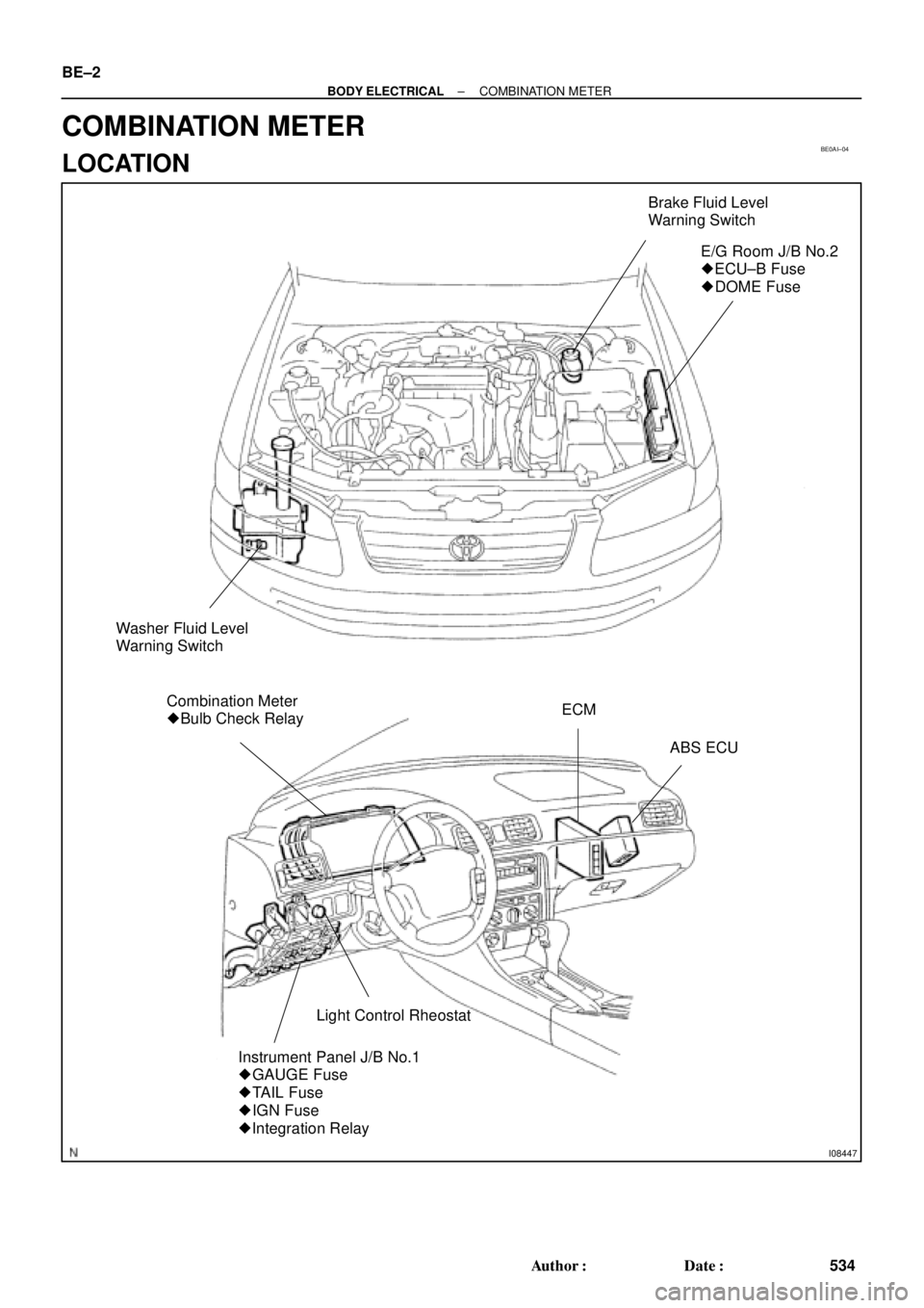
BE0AI±04
I08447
Brake Fluid Level
Warning Switch
E/G Room J/B No.2
� ECU±B Fuse
� DOME Fuse
Washer Fluid Level
Warning Switch
Combination Meter
� Bulb Check RelayECM
ABS ECU
Light Control Rheostat
Instrument Panel J/B No.1
� GAUGE Fuse
� TAIL Fuse
� IGN Fuse
� Integration Relay
BE±2
± BODY ELECTRICALCOMBINATION METER
534 Author�: Date�:
COMBINATION METER
LOCATION
Page 982 of 4592
I08448
PKB Switch
Seat Belt Buckle SwitchDoor Courtesy Switch
Door Courtesy Switch
Light Failure Sensor
Low Oil Pressure Warning Switch
Engine Coolant Temperature
Sender Gauge
Park/Neutral Position Switch
± BODY ELECTRICALCOMBINATION METER
BE±3
535 Author�: Date�:
Page 983 of 4592

BE0AJ±04
Z18937
Connector ºAº Connector ºBº Connector ºCº
Connector ºAº
Connector ºBº
Connector ºCº
J±13±1±A J±16±1 J±13±1
1 2 3 4 5 6 7 8 9 10 11 12 1314 15 16 1 234 56 78 910111213 1 23456 78910111213
C7
C5
A2 B3
A1
C8
B15
C6
B6
A4
C4
B5
C10 B14
A13
B2
C1
B1
C9
A6
A11
A7
A10
A8
A9
C13
B8
B11
B12A5
C11
B4
B16 C2
A12
A3
B7
C3
C12
B9
B10
B13 F
E
T
S
ODOMETER
Fuel Level Warning
Seat Belt Warning
ABS Warning
Low Oil Pressure Warning
Cruise Control Indicator
Malfunction Indicator
O/D OFF Indicator
Light Failure Warning
Brake Warning
SLIP Indicator
TRAC Indicator
Washer Level Warning
Discharge Warning
Right Turn Indicator
Left Turn Indicator
Security Indicator
L
2
D
N
R
P
Illumination
Hi±Beam Indicator
Open Door Warning
SRS Warning
: Fuel Gauge
: Engine Coolant Temperature Sender Gauge
: Tachometer
: Speedometer
No.
A
B
C1
2
3
4
5
6
7 8
9
10
11
12 13
14
15
16
2 3
4
5
6
7 8
9
10
11 12
131
2
3
4 5
6
7
8
9
10
11
12
13
F
E
T
SEngine coolant temperature sender gauge
Ground
Light failure sensor
Integration relay
Traction ECU
Park/neutral position switch (A/T)
O/D OFF switch (A/T)
IGN fuse
Turn signal switch
ST relay
ECM
Generator
Oil pressure switch
ECM
Parking brake switch and brake fluid level warning switch
Headlight dimmer switch
Headlight dimmer switch
Door courtesy switch
DOME fuse
ECU±B fuse
Airbag sensor assembly
ECM
No.1 Vehicle speed sensor Ground
Turn signal switch ECM
Traction ECU
ABS ECU
Ground No.1 Vehicle speed sensor
GAUGE fuse
Igniter
Security ECU
Cruise control ECU
Washer fluid level warning switch
Light control rheostat
TAIL fuse Park/neutral position switch (A/T) Park/neutral position switch (A/T) Park/neutral position switch (A/T) Park/neutral position switch (A/T)
Park/neutral position switch (A/T)Wire Harness Side
Bulb Check
Relay
N20107 N201081
BE±4
± BODY ELECTRICALCOMBINATION METER
CIRCUIT
Page 984 of 4592

BE16U±01
I12031
Ignition
Switch
Fuel
Gauge
BatteryECM
I12029
Ignition
SwitchFuel Gauge
BatteryWire Harness Side
N20212
A
B
C
I12030
BatteryWarning Light
Ignition
Switch
Wire Harness Side
± BODY ELECTRICALCOMBINATION METER
BE±5
INSPECTION
1. INSPECT FUEL RECEIVER GAUGE OPERATION
(a) Disconnect the connector from the ECM.
(b) Turn the ignition switch ON, check that the receiver gauge
needle indicates EMPTY.
(c) Connect terminals 2 on the wire harness side connector
through a 3.4±W test bulb.
(d) Turn the ignition switch ON, check that the bulb lights up
and the receiver gauge needle moves towards the full
side.
HINT:
Because of the silicon oil in the gauge, it will take a short time
for needle to stabilize.
If operation is not as specified, inspect the receiver gauge resis-
tance.
2. INSPECT FUEL RECEIVER GAUGE RESISTANCE
Measure the resistance between terminals.
Tester connectionResistance (W)
A ± BApprox. 270.1
A ± CApprox. 141.3
B ± CApprox. 128.8
If resistance value is not as specified, replace the receiver
gauge.
3. INSPECT FUEL SENDER GAUGE RESISTANCE
(See page SF±36)
4. INSPECT FUEL LEVEL WARNING LIGHT
(a) Disconnect the connector from the sender gauge.
(b) Connect terminals 8 on the wire harness side connector.
(c) Turn the ignition switch ON, check that the warning light
lights up.
If the warning light does not light up, test the bulb or inspect wire
harness.
5. INSPECT FUEL LEVEL WARNING SWITCH
(See page SF±40)
Page 985 of 4592

N20216
C
B
A BE±6
± BODY")
N20215
Engine coolant temperature gauge
Ignition
Switch
BatterySender
Gauge
Z15788
Engine coolant temperature gauge
Ignition
Switch
BatteryWire Harness SideTest Bulb
(3.4 W)
N20216
C
B
A BE±6
± BODY ELECTRICALCOMBINATION METER
6. INSPECT ENGINE COOLANT TEMPERATURE RE-
CEIVER GAUGE OPERATION
(a) Disconnect the connector from the sender gauge.
(b) Turn the ignition switch ON and check that the receiver
gauge needle indicates COOL.
(c) Ground terminal on the wire harness side connector
through a 3.4±W test bulb.
(d) Turn the ignition switch ON, and check that the bulb lights
up and the receiver gauge needle moves to the hot side.
If operation is as specified, replace the sender gauge.
Then, recheck the system.
If operation is not as specified, measure the receiver gauge re-
sistance.
7. INSPECT ENGINE COOLANT TEMPERATURE RE-
CEIVER GAUGE RESISTANCE
Measure the resistance between terminals.
Tester connectionResistance (W) *
A ± BApprox. 175.7
A ± CApprox. 54.0
B ± CApprox. 229.7
*: This circuit includes the diode.
HINT:
Connect the test leads so that the current from the ohmmeter
can flow according to the above order.
If resistance value is not as specified, replace the receiver
gauge.