Page 767 of 4592

N06640
BE1217
Warning Light
Ignition
Switch
Battery
N02346
OFF
ON
1 2
N01212
BE1217
Warning Light
Ignition
Switch
Battery
± BODY ELECTRICALCOMBINATION METER
BE±51
2271 Author�: Date�:
13. INSPECT LOW OIL PRESSURE SWITCH
(a) Disconnect the connector from the switch.
(b) Check that continuity exists between terminal and ground
with the engine stopped.
(c) Check that no continuity exists between terminal and
ground with the engine running.
HINT:
Oil pressure should be over 24.5 kPa (0.25 kgf/cm
2, 3.55 psi).
If operation is not as specified, replace the switch.
14. INSPECT BRAKE SYSTEM WARNING LIGHT
(a) Disconnect the connector from the brake fluid warning
switch.
(b) Release the parking brake pedal.
(c) Connect the terminals on the wire harness side of the lev-
el warning switch connector.
(d) Start the engine, check that the warning light lights up.
If the warning light does not light up, test the bulb or wire har-
ness.
15. INSPECT BRAKE FLUID LEVEL WARNING SWITCH
(a) Remove the reservoir tank cap and strainer.
(b) Disconnect the connector.
(c) Check that no continuity exists between the terminals with
the switch OFF (float up).
(d) Use syphon, etc. to take fluid out of the reservoir tank.
(e) Check that continuity exists between the terminals with
the switch ON (float down).
(f) Pour the fluid back in the reservoir tank.
If operation is not as specified, replace the switch.
16. INSPECT PARKING BRAKE SWITCH
(a) Check that continuity exists between the terminal and
switch body with the switch ON (switch pin released).
(b) Check that no continuity exists between the terminal and
switch body with the switch OFF (switch pin pushed in).
If operation is not as specified, replace the switch or inspect
ground point.
17. INSPECT WASHER FLUID LEVEL WARNING LIGHT
(a) Disconnect the connectors from the level warning switch
and parking brake switch.
(b) Connect terminals on the wire harness side connector of
the level warning switch connector.
(c) Remove the GAUGE fuse and turn the ignition switch ON,
and check that the warning light comes on.
If the warning light does not light up, test the bulb.
Page 768 of 4592

N20217
OFF
ONOhmmeter
Z05732
Warning Light
Ignition
Switch
Battery
1
BE0044
Warning Light
Ignition
Switch
Battery
Z16167
1
2 OFF
ON
N02354
1
2OFF
ON BE±52
± BODY ELECTRICALCOMBINATION METER
2272 Author�: Date�:
18. INSPECT WASHER FLUID LEVEL WARNING SWITCH
(a) Check that no continuity exists between terminals with the
switch OFF (float up).
(b) Check that continuity exists between terminals with the
switch ON (float down).
If operation is not as specified, replace the switch.
19. INSPECT OPEN DOOR WARNING LIGHT
Disconnect the connector from the door courtesy switch and
ground terminal 1 on the wire harness side, and check that the
warning light lights up.
If the warning light does not light up, inspect the bulb or wire har-
ness.
20. INSPECT SEAT BELT WARNING LIGHT
(a) Remove the integration relay from the instrument panel
junction block.
(b) Ground terminal 2 on the integration relay with the con-
nectors still connected.
(c) Turn the ignition switch ON and check that the warning
light lights up.
If the warning light does not light up, inspect the bulb or wire har-
ness.
21. w/o Power seat:
INSPECT BUCKLE SWITCH CONTINUITY
(a) Check that continuity exists between the terminals on the
switch side connector with the switch ON (belt fastened).
(b) Check that no continuity exists between the terminals on
the switch side connector with the switch OFF (belt unfas-
tened).
If operation is not as specified, replace the seat belt inner belt.
22. w/ Power seat:
INSPECT BUCKLE SWITCH CONTINUITY
(a) Check that continuity exists between terminals 1 and 2 on
the switch side connector with the switch ON (belt fas-
tened).
(b) Check that no continuity exists between terminals 1 and
2 on the switch side connector with the switch OFF (belt
unfastened).
If operation is not as specified, replace the seat belt inner belt.
Page 769 of 4592
N20219
Type A:
Type B and C:1
7
9
10
1
7
910
N20220
Type A:
Type B and C:1
7
9
10
1
7910 88
± BODY ELECTRICALCOMBINATION METER
BE±53
2273 Author�: Date�:
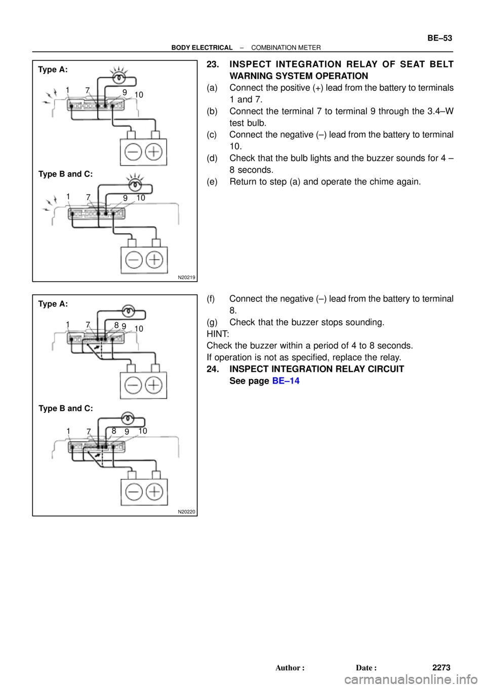
23. INSPECT INTEGRATION RELAY OF SEAT BELT
WARNING SYSTEM OPERATION
(a) Connect the positive (+) lead from the battery to terminals
1 and 7.
(b) Connect the terminal 7 to terminal 9 through the 3.4±W
test bulb.
(c) Connect the negative (±) lead from the battery to terminal
10.
(d) Check that the bulb lights and the buzzer sounds for 4 ±
8 seconds.
(e) Return to step (a) and operate the chime again.
(f) Connect the negative (±) lead from the battery to terminal
8.
(g) Check that the buzzer stops sounding.
HINT:
Check the buzzer within a period of 4 to 8 seconds.
If operation is not as specified, replace the relay.
24. INSPECT INTEGRATION RELAY CIRCUIT
See page BE±14
Page 770 of 4592
N08958
270°
32
1
Z09972
(a)(b)
AB
CAB
C BE±54
± BODY ELECTRICALCOMBINATION METER
2274 Author�: Date�:
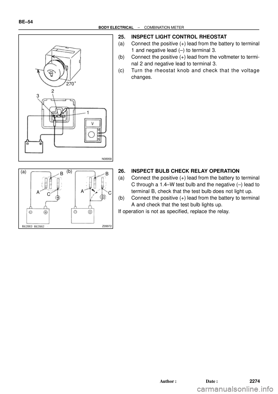
25. INSPECT LIGHT CONTROL RHEOSTAT
(a) Connect the positive (+) lead from the battery to terminal
1 and negative lead (±) to terminal 3.
(b) Connect the positive (+) lead from the voltmeter to termi-
nal 2 and negative lead to terminal 3.
(c) Turn the rheostat knob and check that the voltage
changes.
26. INSPECT BULB CHECK RELAY OPERATION
(a) Connect the positive (+) lead from the battery to terminal
C through a 1.4±W test bulb and the negative (±) lead to
terminal B, check that the test bulb does not light up.
(b) Connect the positive (+) lead from the battery to terminal
A and check that the test bulb lights up.
If operation is not as specified, replace the relay.
Page 772 of 4592

BE0AM±03
N20315
Switch side:
1 2
3
4 5 6
N20314
ON3 4 5
Z08467
1
2
3456 Wire harness side:
S±6±1
N14863
1
2 35 12
35 BE±56
± BODY ELECTRICALDEFOGGER SYSTEM
2276 Author�: Date�:
INSPECTION
1. INSPECT DEFOGGER SWITCH CONTINUITY
Check that is continuity exists between terminals 2 and 6.
If continuity is not as specified, check the bulb.
2. INSPECT DEFOGGER TIMER OPERATION
(a) Connect the positive (+) lead from the battery to terminal
4 and the negative (±) lead to terminal 3.
(b) Connect the positive (+) lead from the battery to terminal
5 through a 3.4±W tester bulb.
(c) Push the defogger switch ON, check that the indicator
light and test bulb light up for 12 to 18 minutes, then the
indicator light and test bulb light goes out.
If operation is not as specified, replace the switch.
3. INSPECT DEFOGGER TIMER CIRCUIT
Disconnect the connector from the switch and inspect the con-
nector on the wire harness side, as shown in the table.
Tester connectionConditionSpecified condition
3 ± GroundConstantContinuity
4 ± GroundIgnition switch LOCK or ACCNo voltage
4 ± GroundIgnition switch ONBattery positive voltage
5 ± GroundIgnition switch LOCK or ACCNo voltage
5 ± GroundIgnition switch ONBattery positive voltage
±Connect terminals 3 and 5.Defogger system operation is normal
If the circuit is not as specified, replace the switch.
4. INSPECT DEFOGGER RELAY CONTINUITY
ConditionTester connectionSpecified condition
Constant1 ± 2Continuity
Apply B+ between
terminals 1 and 2.3 ± 5Continuity
If continuity is not as specified, replace the relay.
Page 777 of 4592

N02358 Unlock
4
8
N02359
4
8
Lock
± BODY ELECTRICALPOWER WINDOW CONTROL SYSTEM
BE±61
2281 Author�: Date�:
Window lock:
Switch positionTester connectionSpecified condition
UP8 ± 9 ± 10Continuity
OFF10 ± 12Continuity
DOWN8 ± 9 ± 12Continuity
(d) Inspect the rear right switch.
Window unlock:
Switch positionTester connectionSpecified condition
UP7 ± 8 ± 9
4 ± 5 ± 14Continuity
OFF4 ± 5 ± 7
4 ± 5 ± 14Continuity
DOWN8 ± 9 ± 14
4 ± 5 ± 7Continuity
Window lock:
Switch positionTester connectionSpecified condition
UP7 ± 8 ± 9Continuity
OFF7 ± 14Continuity
DOWN8 ± 9 ± 14Continuity
If continuity is not as specified, replace the master switch.
2. INSPECT POWER WINDOW MASTER SWITCH ILLU-
MINATION
(a) Set the window lock switch to the unlock position.
(b) Connect the positive (+) lead from the battery to terminal
8 and the negative (±) lead to terminal 4, and check that
all the illuminations light up.
(c) Set the window lock switch to the lock position, check that
all the passenger's power window switch illuminations go
out.
If operation is not as specified, replace the master switch.
Page 828 of 4592
I01474
24 Noise NOISE PRODUCED BY VIBRATION OR SHOCK WHILE DRIVING
Is speaker properly installed?
Is speaker properly installed?
With vehicle stationary lightly tap each system.
Is noise produced?
Noise produced by static electricity accumulated in the vehicle body.Installed properly.
Each system faulty. No
Ye s
No
No Ye s
Ye s BE±112
± BODY ELECTRICALAUDIO SYSTEM
2332 Author�: Date�:
Page 835 of 4592
BE0B2±06
START
Insert the key in the key cylinder.
Under registration
Registration completion
Remove the key.
Will you register the
next key?
NoSecurity indicator blinks until the first
key is inserted. The indicator lights up
after the key registration.
Security Indicator ON
Security Indicator
OFF
END Ye s
Security Indicator ON
(After the last key (sub±key)
has been registered, the indi-
cator goes off.)
± BODY ELECTRICALENGINE IMMOBILISER SYSTEM
BE±119
2339 Author�: Date�:
ENGINE IMMOBILISER SYSTEM
REGISTRATION PROCEDURE
1. KEY REGISTRATION IN AUTOMATIC REGISTRATION MODE
(a) Registration of a new transponder key.
HINT:
�This must be done when you have installed a new ECM.
�The new ECM is in the automatic key code registration mode. The already fixed number of key codes
for this ECM can be registered.
On this type of vehicle, up to 4 key codes can be registered.
�In the automatic registration mode, the last key registered becomes sub±key.