1999 NISSAN PRIMERA ESP
[x] Cancel search: ESPPage 876 of 2267
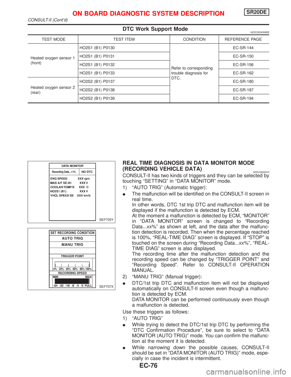
DTC Work Support ModeNCEC0034S0802
TEST MODE TEST ITEM CONDITION REFERENCE PAGE
Heated oxygen sensor 1
(front)HO2S1 (B1) P0130
Refer to corresponding
trouble diagnosis for
DTC.EC-SR-144
HO2S1 (B1) P0131 EC-SR-150
HO2S1 (B1) P0132 EC-SR-156
HO2S1 (B1) P0133 EC-SR-162
Heated oxygen sensor 2
(rear)HO2S2 (B1) P0137 EC-SR-180
HO2S2 (B1) P0138 EC-SR-187
HO2S2 (B1) P0139 EC-SR-194
REAL TIME DIAGNOSIS IN DATA MONITOR MODE
(RECORDING VEHICLE DATA)
NCEC0034S10CONSULT-II has two kinds of triggers and they can be selected by
touching ªSETTINGº in ªDATA MONITORº mode.
1) ªAUTO TRIGº (Automatic trigger):
IThe malfunction will be identified on the CONSULT-II screen in
real time.
In other words, DTC 1st trip DTC and malfunction item will be
displayed if the malfunction is detected by ECM.
At the moment a malfunction is detected by ECM, ªMONITORº
in ªDATA MONITORº screen is changed to ªRecording
Data...xx%º as shown at left, and the data after the malfunc-
tion detection is recorded. Then when the percentage reached
is 100%, ªREAL-TIME DIAGº screen is displayed. If ªSTOPº is
touched on the screen during ªRecording Data...xx%º, ªREAL-
TIME DIAGº screen is also displayed.
The recording time after the malfunction detection and the
recording speed can be changed by ªTRIGGER POINTº and
ªRecording Speedº. Refer to CONSULT-II OPERATION
MANUAL.
2) ªMANU TRIGº (Manual trigger):
IDTC/1st trip DTC and malfunction item will not be displayed
automatically on CONSULT-II screen even though a malfunc-
tion is detected by ECM.
DATA MONITOR can be performed continuously even though
a malfunction is detected.
Use these triggers as follows:
1) ªAUTO TRIGº
IWhile trying to detect the DTC/1st trip DTC by performing the
ªDTC Confirmation Procedureº, be sure to select to ªDATA
MONITOR (AUTO TRIG)º mode. You can confirm the malfunc-
tion at the moment it is detected.
IWhile narrowing down the possible causes, CONSULT-II
should be set in ªDATA MONITOR (AUTO TRIG)º mode, espe-
cially in case the incident is intermittent.
SEF705Y
SEF707X
ON BOARD DIAGNOSTIC SYSTEM DESCRIPTIONSR20DE
CONSULT-II (Cont'd)
EC-76
Page 880 of 2267

IntroductionNCEC0036The engine has an ECM to control major systems such as fuel
control, ignition control, idle air control system, etc. The ECM
accepts input signals from sensors and instantly drives actuators.
It is essential that both input and output signals are proper and
stable. At the same time, it is important that there are no problems
such as vacuum leaks, fouled spark plugs, or other problems with
the engine.
It is much more difficult to diagnose a problem that occurs intermit-
tently rather than continuously. Most intermittent problems are
caused by poor electric connections or improper wiring. In this
case, careful checking of suspected circuits may help prevent the
replacement of good parts.
A visual check only may not find the cause of the problems. A road
test with CONSULT-II (or GST) or a circuit tester connected should
be performed. Follow the ªWork Flowº on EC-SR-82.
Before undertaking actual checks, take a few minutes to talk with
a customer who approaches with a driveability complaint. The cus-
tomer can supply good information about such problems, espe-
cially intermittent ones. Find out what symptoms are present and
under what conditions they occur. A ªDiagnostic Worksheetº like the
example on next page should be used.
Start your diagnosis by looking for ªconventionalº problems first.
This will help troubleshoot driveability problems on an electronically
controlled engine vehicle.
DIAGNOSTIC WORKSHEETNCEC0036S01There are many operating conditions that lead to the malfunction
of engine components. A good grasp of such conditions can make
trouble-shooting faster and more accurate.
In general, each customer feels differently about a problem. It is
important to fully understand the symptoms or conditions for a
customer complaint.
Utilize a diagnostic worksheet like the one on the next page in order
to organize all the information for troubleshooting.
Some conditions may cause the malfunction indicator to come on
steady or blink and DTC to be detected.
Example:
Vehicle ran out of fuel, which caused the engine to misfire.
MEF036D
SEF233G
SEF234G
SEF907L
KEY POINTS
WHAT..... Vehicle & engine model
WHEN..... Date, Frequencies
WHERE..... Road conditions
HOW..... Operating conditions,
Weather conditions,
Symptoms
TROUBLE DIAGNOSIS Ð INTRODUCTIONSR20DE
Introduction
EC-80
Page 888 of 2267
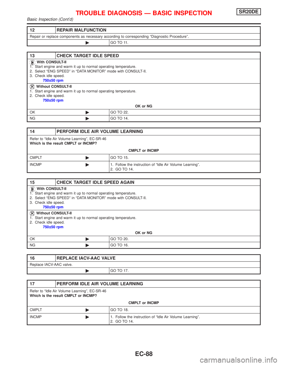
12 REPAIR MALFUNCTION
Repair or replace components as necessary according to corresponding ªDiagnostic Procedureº.
©GO TO 11.
13 CHECK TARGET IDLE SPEED
With CONSULT-II
1. Start engine and warm it up to normal operating temperature.
2. Select ªENG SPEEDº in ªDATA MONITORº mode with CONSULT-II.
3. Check idle speed.
750 50 rpm
Without CONSULT-II
1. Start engine and warm it up to normal operating temperature.
2. Check idle speed.
750 50 rpm
OK or NG
OK©GO TO 22.
NG©GO TO 14.
14 PERFORM IDLE AIR VOLUME LEARNING
Refer to ªIdle Air Volume Learningº, EC-SR-46
Which is the result CMPLT or INCMP?
CMPLT or INCMP
CMPLT©GO TO 15.
INCMP©1. Follow the instruction of ªIdle Air Volume Learningº.
2. GO TO 14.
15 CHECK TARGET IDLE SPEED AGAIN
With CONSULT-II
1. Start engine and warm it up to normal operating temperature.
2. Select ªENG SPEEDº in ªDATA MONITORº mode with CONSULT-II.
3. Check idle speed.
750 50 rpm
Without CONSULT-II
1. Start engine and warm it up to normal operating temperature.
2. Check idle speed.
750 50 rpm
OK or NG
OK©GO TO 20.
NG©GO TO 16.
16 REPLACE IACV-AAC VALVE
Replace IACV-AAC valve.
©GO TO 17.
17 PERFORM IDLE AIR VOLUME LEARNING
Refer to ªIdle Air Volume Learningº, EC-SR-46
Which is the result CMPLT or INCMP?
CMPLT or INCMP
CMPLT©GO TO 18.
INCMP©1. Follow the instruction of ªIdle Air Volume Learningº.
2. GO TO 14.
TROUBLE DIAGNOSIS Ð BASIC INSPECTIONSR20DE
Basic Inspection (Cont'd)
EC-88
Page 926 of 2267
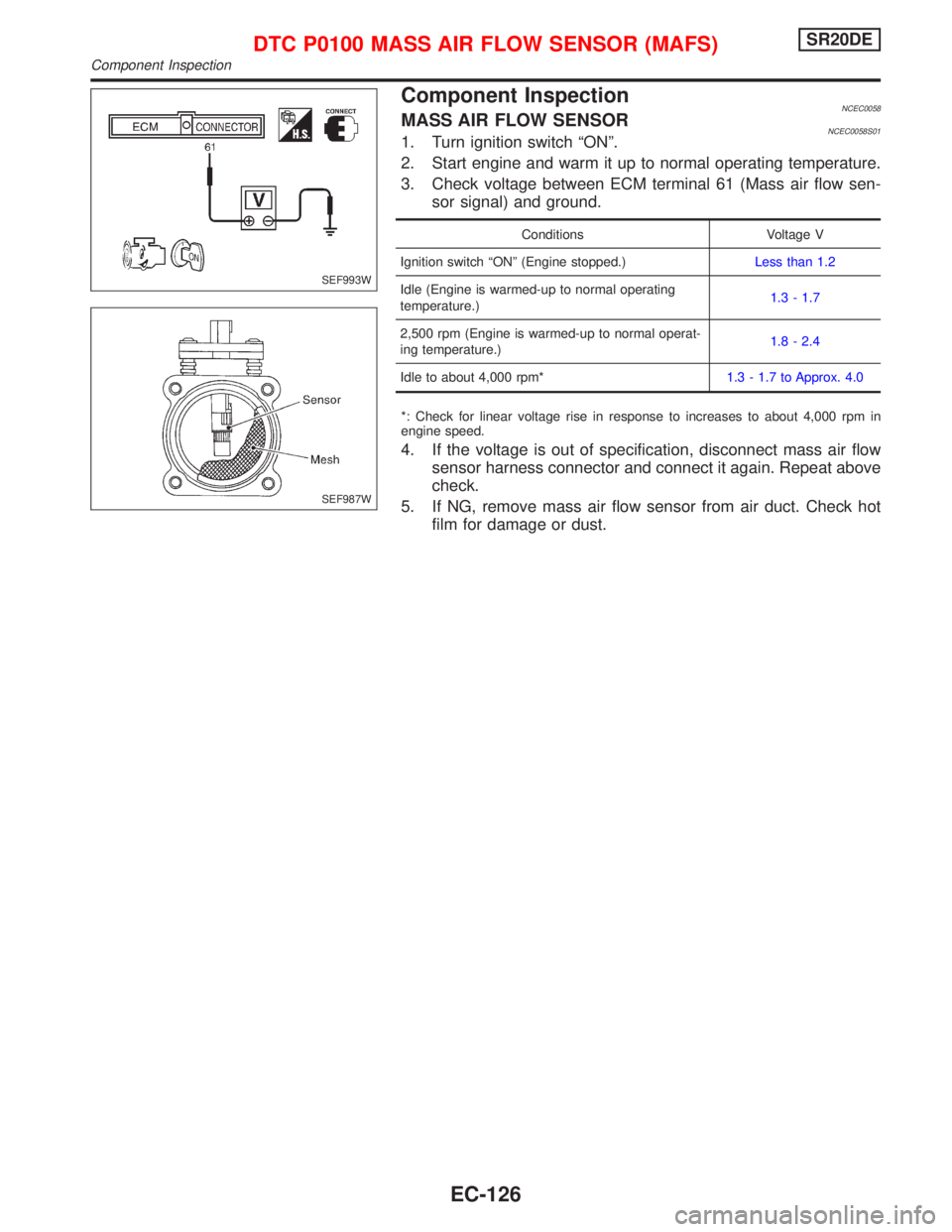
Component InspectionNCEC0058MASS AIR FLOW SENSORNCEC0058S011. Turn ignition switch ªONº.
2. Start engine and warm it up to normal operating temperature.
3. Check voltage between ECM terminal 61 (Mass air flow sen-
sor signal) and ground.
Conditions Voltage V
Ignition switch ªONº (Engine stopped.)Less than 1.2
Idle (Engine is warmed-up to normal operating
temperature.)1.3 - 1.7
2,500 rpm (Engine is warmed-up to normal operat-
ing temperature.)1.8 - 2.4
Idle to about 4,000 rpm*1.3 - 1.7 to Approx. 4.0
*: Check for linear voltage rise in response to increases to about 4,000 rpm in
engine speed.
4. If the voltage is out of specification, disconnect mass air flow
sensor harness connector and connect it again. Repeat above
check.
5. If NG, remove mass air flow sensor from air duct. Check hot
film for damage or dust.
SEF993W
SEF987W
DTC P0100 MASS AIR FLOW SENSOR (MAFS)SR20DE
Component Inspection
EC-126
Page 927 of 2267
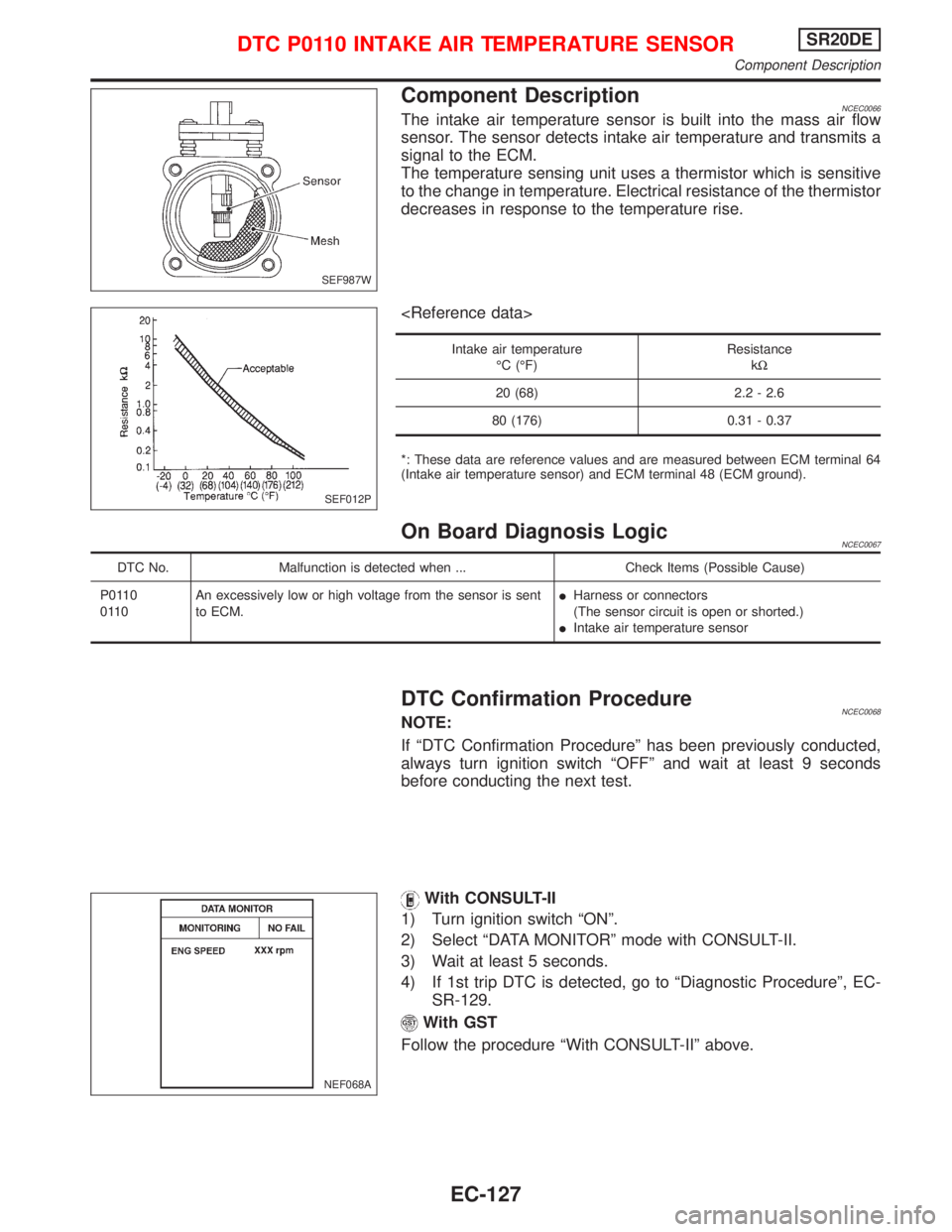
Component DescriptionNCEC0066The intake air temperature sensor is built into the mass air flow
sensor. The sensor detects intake air temperature and transmits a
signal to the ECM.
The temperature sensing unit uses a thermistor which is sensitive
to the change in temperature. Electrical resistance of the thermistor
decreases in response to the temperature rise.
Intake air temperature
ÉC (ÉF)Resistance
kW
20 (68) 2.2 - 2.6
80 (176) 0.31 - 0.37
*: These data are reference values and are measured between ECM terminal 64
(Intake air temperature sensor) and ECM terminal 48 (ECM ground).
On Board Diagnosis LogicNCEC0067
DTC No. Malfunction is detected when ... Check Items (Possible Cause)
P0110
0110An excessively low or high voltage from the sensor is sent
to ECM.IHarness or connectors
(The sensor circuit is open or shorted.)
IIntake air temperature sensor
DTC Confirmation ProcedureNCEC0068NOTE:
If ªDTC Confirmation Procedureº has been previously conducted,
always turn ignition switch ªOFFº and wait at least 9 seconds
before conducting the next test.
With CONSULT-II
1) Turn ignition switch ªONº.
2) Select ªDATA MONITORº mode with CONSULT-II.
3) Wait at least 5 seconds.
4) If 1st trip DTC is detected, go to ªDiagnostic Procedureº, EC-
SR-129.
With GST
Follow the procedure ªWith CONSULT-IIº above.
SEF987W
SEF012P
NEF068A
DTC P0110 INTAKE AIR TEMPERATURE SENSORSR20DE
Component Description
EC-127
Page 937 of 2267
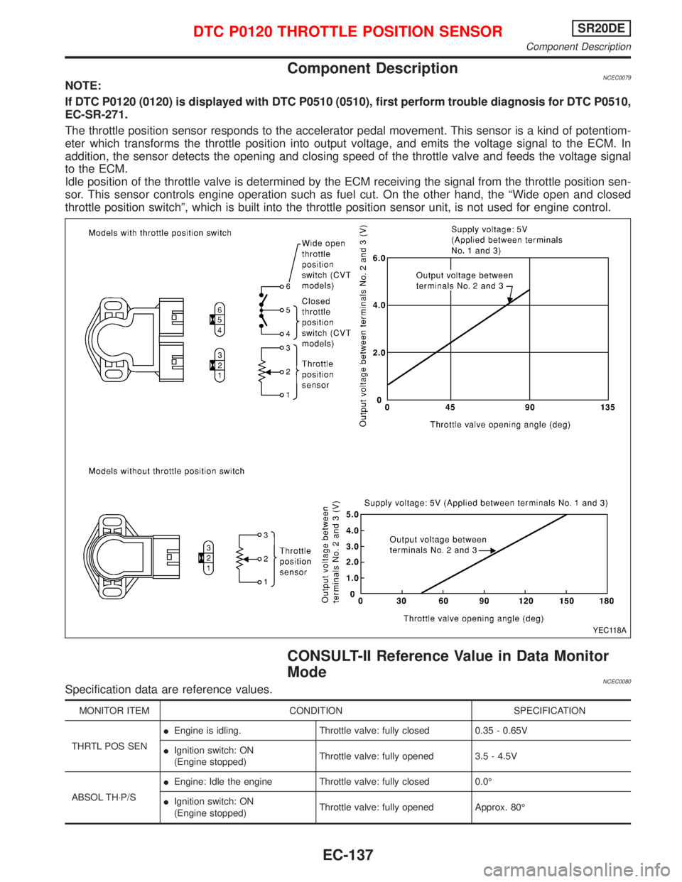
Component DescriptionNCEC0079NOTE:
If DTC P0120 (0120) is displayed with DTC P0510 (0510), first perform trouble diagnosis for DTC P0510,
EC-SR-271.
The throttle position sensor responds to the accelerator pedal movement. This sensor is a kind of potentiom-
eter which transforms the throttle position into output voltage, and emits the voltage signal to the ECM. In
addition, the sensor detects the opening and closing speed of the throttle valve and feeds the voltage signal
to the ECM.
Idle position of the throttle valve is determined by the ECM receiving the signal from the throttle position sen-
sor. This sensor controls engine operation such as fuel cut. On the other hand, the ªWide open and closed
throttle position switchº, which is built into the throttle position sensor unit, is not used for engine control.
CONSULT-II Reference Value in Data Monitor
Mode
NCEC0080Specification data are reference values.
MONITOR ITEM CONDITION SPECIFICATION
THRTL POS SENIEngine is idling. Throttle valve: fully closed 0.35 - 0.65V
IIgnition switch: ON
(Engine stopped)Throttle valve: fully opened 3.5 - 4.5V
ABSOL TH×P/SIEngine: Idle the engine Throttle valve: fully closed 0.0É
IIgnition switch: ON
(Engine stopped)Throttle valve: fully opened Approx. 80É
YEC118A
DTC P0120 THROTTLE POSITION SENSORSR20DE
Component Description
EC-137
Page 962 of 2267
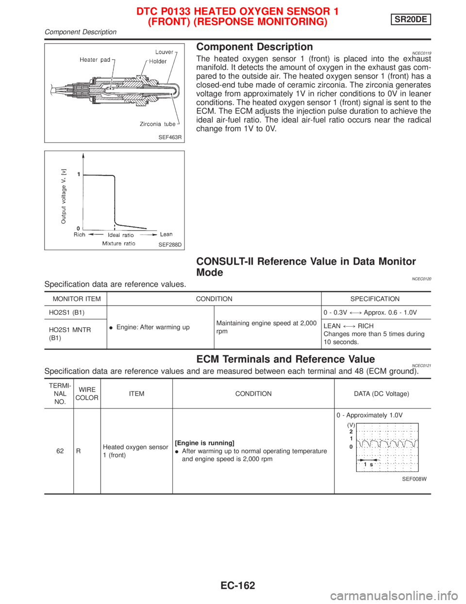
Component DescriptionNCEC0119The heated oxygen sensor 1 (front) is placed into the exhaust
manifold. It detects the amount of oxygen in the exhaust gas com-
pared to the outside air. The heated oxygen sensor 1 (front) has a
closed-end tube made of ceramic zirconia. The zirconia generates
voltage from approximately 1V in richer conditions to 0V in leaner
conditions. The heated oxygen sensor 1 (front) signal is sent to the
ECM. The ECM adjusts the injection pulse duration to achieve the
ideal air-fuel ratio. The ideal air-fuel ratio occurs near the radical
change from 1V to 0V.
CONSULT-II Reference Value in Data Monitor
Mode
NCEC0120Specification data are reference values.
MONITOR ITEM CONDITION SPECIFICATION
HO2S1 (B1)
IEngine: After warming upMaintaining engine speed at 2,000
rpm0 - 0.3V+,Approx. 0.6 - 1.0V
HO2S1 MNTR
(B1)LEAN+,RICH
Changes more than 5 times during
10 seconds.
ECM Terminals and Reference ValueNCEC0121Specification data are reference values and are measured between each terminal and 48 (ECM ground).
TERMI-
NAL
NO.WIRE
COLORITEM CONDITION DATA (DC Voltage)
62 RHeated oxygen sensor
1 (front)[Engine is running]
IAfter warming up to normal operating temperature
and engine speed is 2,000 rpm0 - Approximately 1.0V
SEF008W
SEF463R
SEF288D
DTC P0133 HEATED OXYGEN SENSOR 1
(FRONT) (RESPONSE MONITORING)SR20DE
Component Description
EC-162
Page 963 of 2267
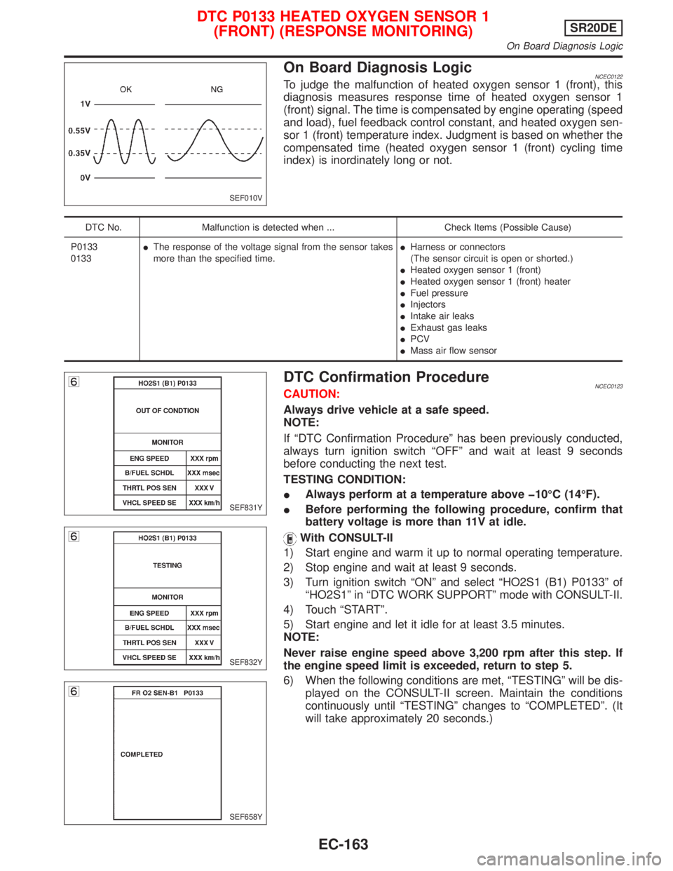
On Board Diagnosis LogicNCEC0122To judge the malfunction of heated oxygen sensor 1 (front), this
diagnosis measures response time of heated oxygen sensor 1
(front) signal. The time is compensated by engine operating (speed
and load), fuel feedback control constant, and heated oxygen sen-
sor 1 (front) temperature index. Judgment is based on whether the
compensated time (heated oxygen sensor 1 (front) cycling time
index) is inordinately long or not.
DTC No. Malfunction is detected when ... Check Items (Possible Cause)
P0133
0133IThe response of the voltage signal from the sensor takes
more than the specified time.IHarness or connectors
(The sensor circuit is open or shorted.)
IHeated oxygen sensor 1 (front)
IHeated oxygen sensor 1 (front) heater
IFuel pressure
IInjectors
IIntake air leaks
IExhaust gas leaks
IPCV
IMass air flow sensor
DTC Confirmation ProcedureNCEC0123CAUTION:
Always drive vehicle at a safe speed.
NOTE:
If ªDTC Confirmation Procedureº has been previously conducted,
always turn ignition switch ªOFFº and wait at least 9 seconds
before conducting the next test.
TESTING CONDITION:
IAlways perform at a temperature above þ10ÉC (14ÉF).
IBefore performing the following procedure, confirm that
battery voltage is more than 11V at idle.
With CONSULT-II
1) Start engine and warm it up to normal operating temperature.
2) Stop engine and wait at least 9 seconds.
3) Turn ignition switch ªONº and select ªHO2S1 (B1) P0133º of
ªHO2S1º in ªDTC WORK SUPPORTº mode with CONSULT-II.
4) Touch ªSTARTº.
5) Start engine and let it idle for at least 3.5 minutes.
NOTE:
Never raise engine speed above 3,200 rpm after this step. If
the engine speed limit is exceeded, return to step 5.
6) When the following conditions are met, ªTESTINGº will be dis-
played on the CONSULT-II screen. Maintain the conditions
continuously until ªTESTINGº changes to ªCOMPLETEDº. (It
will take approximately 20 seconds.)
SEF010V
SEF831Y
SEF832Y
SEF658Y
DTC P0133 HEATED OXYGEN SENSOR 1
(FRONT) (RESPONSE MONITORING)SR20DE
On Board Diagnosis Logic
EC-163