Page 964 of 2267
ENG SPEED 1,800 - 2,900 rpm (CVT)
2,000 - 3,100 rpm (M/T)
Vehicle speed 80 - 120 km/h (50 - 75 MPH)
B/FUEL SCHDL 4.5 - 14.0 msec (CVT)
3.5 - 12.0 msec (M/T)
Selector lever Suitable position
If ªTESTINGº is not displayed after 5 minutes, retry from
step 2.
7) Make sure that ªOKº is displayed after touching ªSELF-DIAG
RESULTSº. If ªNGº is displayed, refer to ªDiagnostic
Procedureº, EC-SR-166.
Overall Function CheckNCEC0124Use this procedure to check the overall function of the heated oxy-
gen sensor 1 (front) circuit. During this check, a 1st trip DTC might
not be confirmed.
Without CONSULT-II
1) Start engine and warm it up to normal operating temperature.
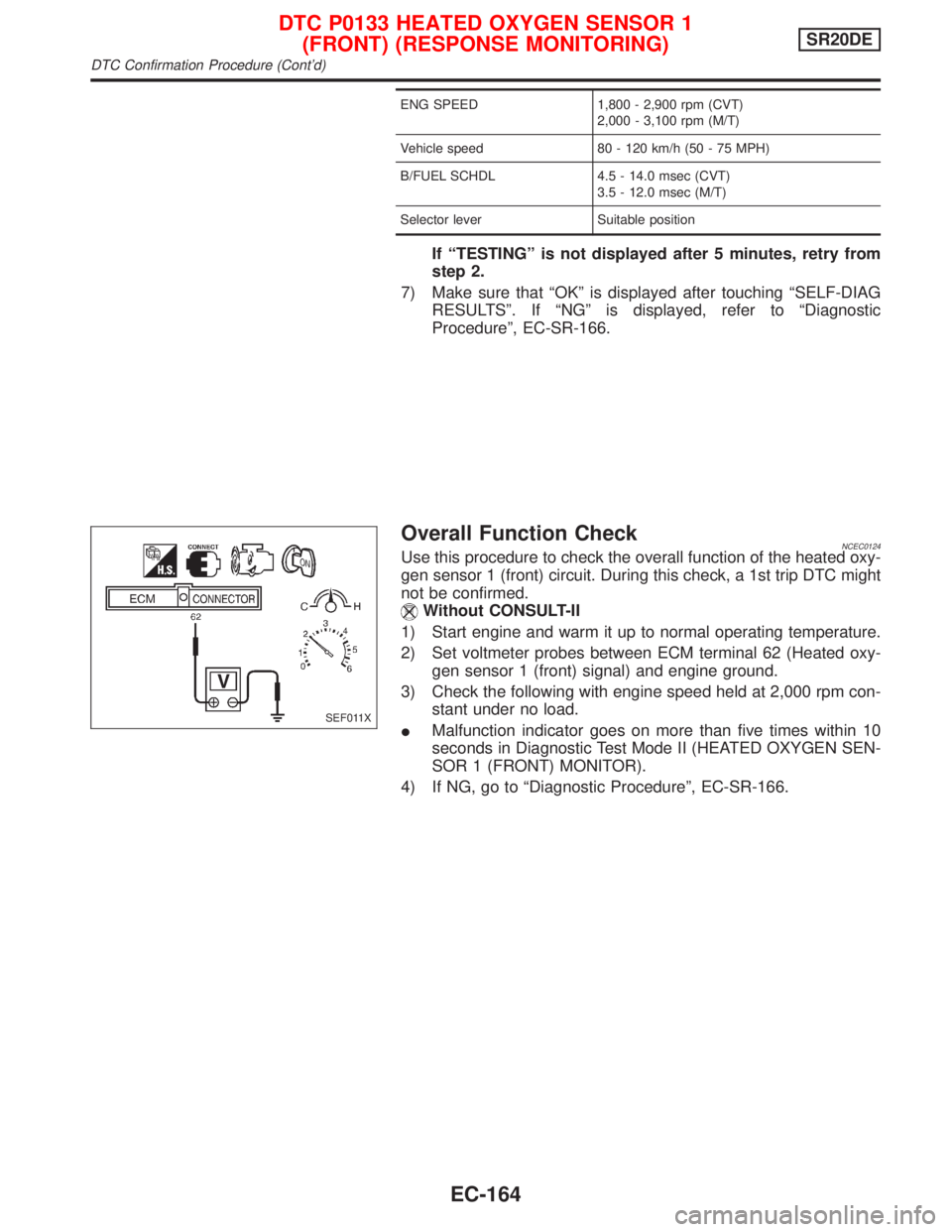
2) Set voltmeter probes between ECM terminal 62 (Heated oxy-
gen sensor 1 (front) signal) and engine ground.
3) Check the following with engine speed held at 2,000 rpm con-
stant under no load.
IMalfunction indicator goes on more than five times within 10
seconds in Diagnostic Test Mode II (HEATED OXYGEN SEN-
SOR 1 (FRONT) MONITOR).
4) If NG, go to ªDiagnostic Procedureº, EC-SR-166.
SEF011X
DTC P0133 HEATED OXYGEN SENSOR 1
(FRONT) (RESPONSE MONITORING)SR20DE
DTC Confirmation Procedure (Cont'd)
EC-164
Page 965 of 2267
Wiring DiagramNCEC0125
YEC084A
DTC P0133 HEATED OXYGEN SENSOR 1
(FRONT) (RESPONSE MONITORING)SR20DE
Wiring Diagram
EC-165
Page 966 of 2267
Diagnostic ProcedureNCEC0126
1 RETIGHTEN GROUND SCREWS
1. Turn ignition switch ªOFFº.
2. Loosen and retighten engine ground screws.
SEF202X
©GO TO 2.
2 RETIGHTEN HEATED OXYGEN SENSOR 1 (FRONT)
Loosen and retighten heated oxygen sensor 1 (front).
Tightening torque:
40-60N×m (4.1 - 6.1 kg-m, 30 - 44 ft-lb)
©GO TO 3.
3 CHECK EXHAUST AIR LEAK
1. Start engine and run it at idle.
2. Listen for an exhaust air leak before three way catalyst.
SEF099P
OK or NG
OK©GO TO 4.
NG©Repair or replace.
4 CHECK FOR INTAKE AIR LEAK
Listen for an intake air leak after the mass air flow sensor.
OK or NG
OK©GO TO 5.
NG©Repair or replace.
Intake manifold
collector
Engine
ground
DTC P0133 HEATED OXYGEN SENSOR 1
(FRONT) (RESPONSE MONITORING)SR20DE
Diagnostic Procedure
EC-166
Page 967 of 2267
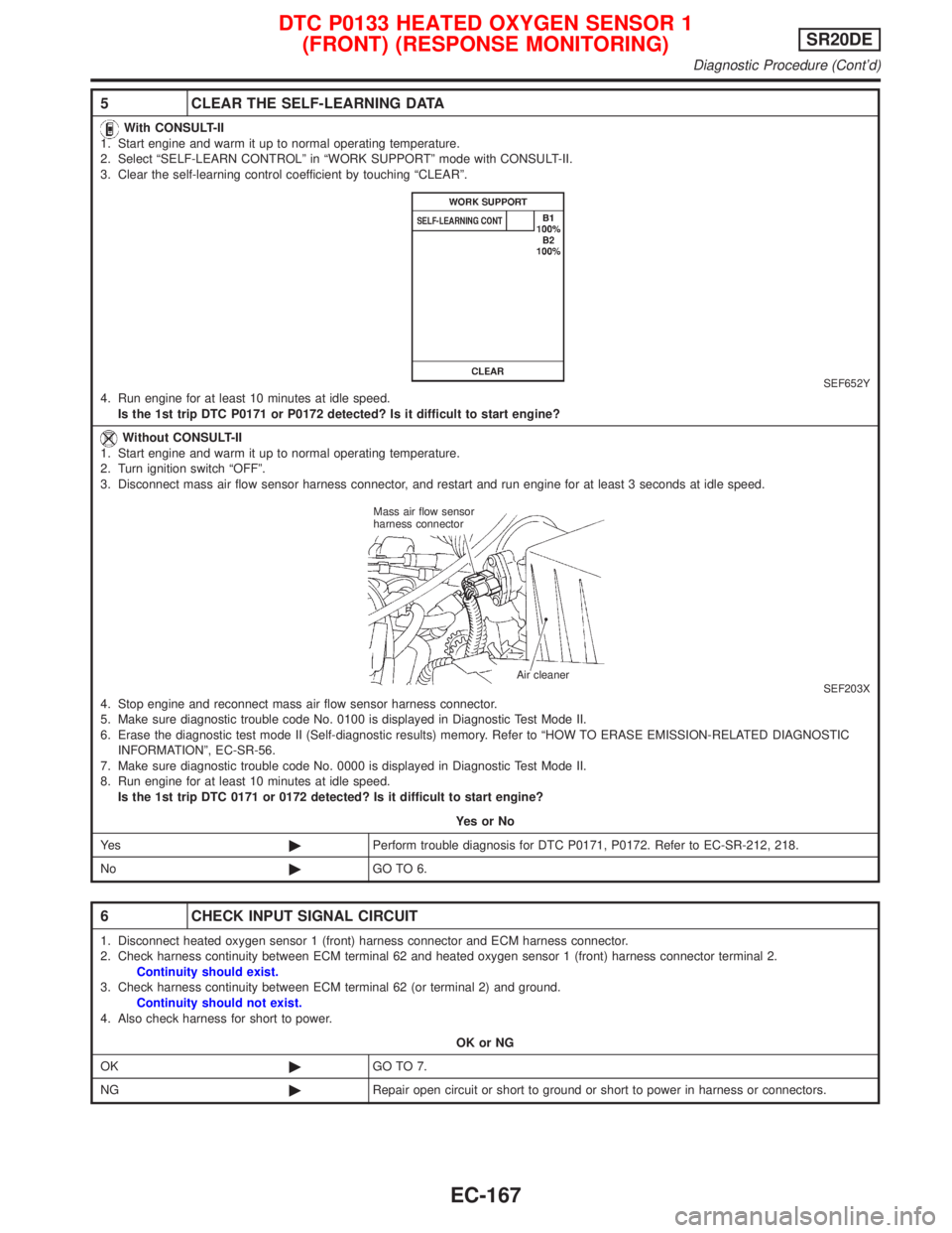
5 CLEAR THE SELF-LEARNING DATA
With CONSULT-II
1. Start engine and warm it up to normal operating temperature.
2. Select ªSELF-LEARN CONTROLº in ªWORK SUPPORTº mode with CONSULT-II.
3. Clear the self-learning control coefficient by touching ªCLEARº.
SEF652Y4. Run engine for at least 10 minutes at idle speed.
Is the 1st trip DTC P0171 or P0172 detected? Is it difficult to start engine?
Without CONSULT-II
1. Start engine and warm it up to normal operating temperature.
2. Turn ignition switch ªOFFº.
3. Disconnect mass air flow sensor harness connector, and restart and run engine for at least 3 seconds at idle speed.
SEF203X4. Stop engine and reconnect mass air flow sensor harness connector.
5. Make sure diagnostic trouble code No. 0100 is displayed in Diagnostic Test Mode II.
6. Erase the diagnostic test mode II (Self-diagnostic results) memory. Refer to ªHOW TO ERASE EMISSION-RELATED DIAGNOSTIC
INFORMATIONº, EC-SR-56.
7. Make sure diagnostic trouble code No. 0000 is displayed in Diagnostic Test Mode II.
8. Run engine for at least 10 minutes at idle speed.
Is the 1st trip DTC 0171 or 0172 detected? Is it difficult to start engine?
YesorNo
Ye s©Perform trouble diagnosis for DTC P0171, P0172. Refer to EC-SR-212, 218.
No©GO TO 6.
6 CHECK INPUT SIGNAL CIRCUIT
1. Disconnect heated oxygen sensor 1 (front) harness connector and ECM harness connector.
2. Check harness continuity between ECM terminal 62 and heated oxygen sensor 1 (front) harness connector terminal 2.
Continuity should exist.
3. Check harness continuity between ECM terminal 62 (or terminal 2) and ground.
Continuity should not exist.
4. Also check harness for short to power.
OK or NG
OK©GO TO 7.
NG©Repair open circuit or short to ground or short to power in harness or connectors.
Mass air flow sensor
harness connector
Air cleaner
DTC P0133 HEATED OXYGEN SENSOR 1
(FRONT) (RESPONSE MONITORING)SR20DE
Diagnostic Procedure (Cont'd)
EC-167
Page 968 of 2267
7 CHECK HEATED OXYGEN SENSOR 1 (FRONT) HEATER
Refer to ªComponent Inspectionº, EC-SR-179.
OK or NG
OK©GO TO 8.
NG©Replace heated oxygen sensor 1 (front).
8 CHECK HEATED OXYGEN SENSOR 1 (FRONT)
Refer to ªComponent Inspectionº, EC-SR-169.
OK or NG
OK©GO TO 9.
NG©Replace heated oxygen sensor 1 (front).
9 CHECK MASS AIR FLOW SENSOR
Refer to ªComponent Inspectionº, EC-SR-126.
OK or NG
OK©GO TO 10.
NG©Replace mass air flow sensor.
10 CHECK PCV VALVE
Refer to ªPositive Crankcase Ventilationº, EC-SR-30.
OK or NG
OK©GO TO 11.
NG©Repair or replace PCV valve.
11 CHECK INTERMITTENT INCIDENT
Perform ªTROUBLE DIAGNOSIS FOR INTERMITTENT INCIDENTº, EC-SR-114.
©INSPECTION END
DTC P0133 HEATED OXYGEN SENSOR 1
(FRONT) (RESPONSE MONITORING)SR20DE
Diagnostic Procedure (Cont'd)
EC-168
Page 969 of 2267
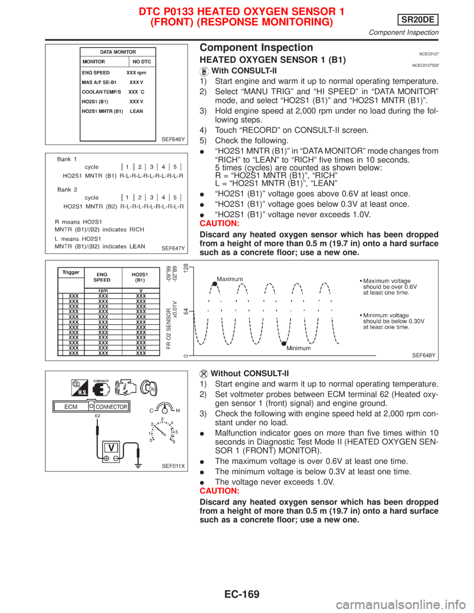
Component InspectionNCEC0127HEATED OXYGEN SENSOR 1 (B1)NCEC0127S02With CONSULT-II
1) Start engine and warm it up to normal operating temperature.
2) Select ªMANU TRIGº and ªHI SPEEDº in ªDATA MONITORº
mode, and select ªHO2S1 (B1)º and ªHO2S1 MNTR (B1)º.
3) Hold engine speed at 2,000 rpm under no load during the fol-
lowing steps.
4) Touch ªRECORDº on CONSULT-II screen.
5) Check the following.
IªHO2S1 MNTR (B1)º in ªDATA MONITORº mode changes from
ªRICHº to ªLEANº to ªRICHº five times in 10 seconds.
5 times (cycles) are counted as shown below:
R = ªHO2S1 MNTR (B1)º, ªRICHº
L = ªHO2S1 MNTR (B1)º, ªLEANº
IªHO2S1 (B1)º voltage goes above 0.6V at least once.
IªHO2S1 (B1)º voltage goes below 0.3V at least once.
IªHO2S1 (B1)º voltage never exceeds 1.0V.
CAUTION:
Discard any heated oxygen sensor which has been dropped
from a height of more than 0.5 m (19.7 in) onto a hard surface
such as a concrete floor; use a new one.
Without CONSULT-II
1) Start engine and warm it up to normal operating temperature.
2) Set voltmeter probes between ECM terminal 62 (Heated oxy-
gen sensor 1 (front) signal) and engine ground.
3) Check the following with engine speed held at 2,000 rpm con-
stant under no load.
IMalfunction indicator goes on more than five times within 10
seconds in Diagnostic Test Mode II (HEATED OXYGEN SEN-
SOR 1 (FRONT) MONITOR).
IThe maximum voltage is over 0.6V at least one time.
IThe minimum voltage is below 0.3V at least one time.
IThe voltage never exceeds 1.0V.
CAUTION:
Discard any heated oxygen sensor which has been dropped
from a height of more than 0.5 m (19.7 in) onto a hard surface
such as a concrete floor; use a new one.
SEF646Y
SEF647Y
SEF648Y
FR O2 SENSOR
x0.01V-09²99
-02²89
SEF011X
DTC P0133 HEATED OXYGEN SENSOR 1
(FRONT) (RESPONSE MONITORING)SR20DE
Component Inspection
EC-169
Page 975 of 2267
DescriptionNCEC0136SYSTEM DESCRIPTIONNCEC0136S01
Sensor Input Signal to ECMECM func-
tionActuator
Camshaft position sensor Engine speedHeated oxy-
gen sensor
1 (front)
heater con-
trolHeated oxygen sensor 1 (front)
heater
The ECM performs ON/OFF control of the heated oxygen sensor 1 (front) heater corresponding to the engine
operating condition.
OPERATIONNCEC0136S02
Engine speed Heated oxygen sensor 1 (front) heater
Above 3,200 rpm OFF
More than 20 seconds after exceeding 3,200 rpm ON
CONSULT-II Reference Value in Data Monitor
Mode
NCEC0137Specification data are reference values.
MONITOR ITEM CONDITION SPECIFICATION
HO2S2 HTR (B1)IEngine speed: Below 3,200 rpm ON
IMore than 20 seconds after exceeding 3,200 rpm OFF
ECM Terminals and Reference ValueNCEC0138Specification data are reference values and are measured between each terminal and 48 (ECM ground).
TERMI-
NAL NO.WIRE
COLORITEM CONDITION DATA (DC Voltage)
4LHeated oxygen sensor 1
(front) heater[Engine is running]
IEngine speed is below 3,200 rpm.Approximately 0V
[Engine is running]
IMore than 20 seconds after exceeding
3,200 rpm.BATTERY VOLTAGE
(11 - 14V)
On Board Diagnosis LogicNCEC0139
DTC No. Malfunction is detected when ... Check Items (Possible Cause)
P0135
0135IThe current amperage in the heated oxygen sensor 1
(front) heater circuit is out of the normal range.
(An improper voltage drop signal is sent to ECM through
the heated oxygen sensor 1 (front) heater.)IHarness or connectors
(The heated oxygen sensor 1 (front) heater cir-
cuit is open or shorted.)
IHeated oxygen sensor 1 (front) heater
DTC Confirmation ProcedureNCEC0140NOTE:
If ªDTC Confirmation Procedureº has been previously conducted,
always turn ignition switch ªOFFº and wait at least 9 seconds
before conducting the next test.
TESTING CONDITION:
Before performing the following procedure, confirm that bat-
tery voltage is between 10.5V and 16V at idle.
DTC P0135 HEATED OXYGEN SENSOR 1 (FRONT) HEATERSR20DE
Description
EC-175
Page 994 of 2267
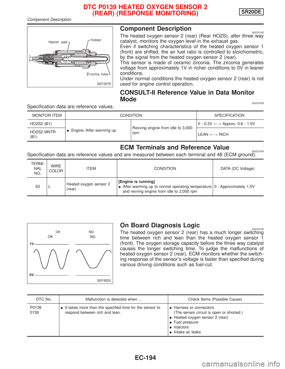
Component DescriptionNCEC0162The heated oxygen sensor 2 (rear) (Rear HO2S), after three way
catalyst, monitors the oxygen level in the exhaust gas.
Even if switching characteristics of the heated oxygen sensor 1
(front) are shifted, the air fuel ratio is controlled to stoichiometric,
by the signal from the heated oxygen sensor 2 (rear).
This sensor is made of ceramic zirconia. The zirconia generates
voltage from approximately 1V in richer conditions to 0V in leaner
conditions.
Under normal conditions the heated oxygen sensor 2 (rear) is not
used for engine control operation.
CONSULT-II Reference Value in Data Monitor
Mode
NCEC0163Specification data are reference values.
MONITOR ITEM CONDITION SPECIFICATION
HO2S2 (B1)
IEngine: After warming upRevving engine from idle to 3,000
rpm0 - 0.3V+,Approx. 0.6 - 1.0V
HO2S2 MNTR
(B1)LEAN+,RICH
ECM Terminals and Reference ValueNCEC0164Specification data are reference values and are measured between each terminal and 48 (ECM ground).
TERMI-
NAL
NO.WIRE
COLORITEM CONDITION DATA (DC Voltage)
63 LHeated oxygen sensor 2
(rear)[Engine is running]
IAfter warming up to normal operating temperature
and revving engine from idle to 2,000 rpm0 - Approximately 1.0V
On Board Diagnosis LogicNCEC0165The heated oxygen sensor 2 (rear) has a much longer switching
time between rich and lean than the heated oxygen sensor 1
(front). The oxygen storage capacity before the three way catalyst
causes the longer switching time. To judge the malfunctions of
heated oxygen sensor 2 (rear), ECM monitors whether the switch-
ing response of the sensor's voltage is faster than specified during
various driving conditions such as fuel-cut.
DTC No. Malfunction is detected when ... Check Items (Possible Cause)
P0139
0139IIt takes more than the specified time for the sensor to
respond between rich and lean.IHarness or connectors
(The sensor circuit is open or shorted.)
IHeated oxygen sensor 2 (rear)
IFuel pressure
IInjectors
IIntake air leaks
SEF327R
SEF302U OK NG
DTC P0139 HEATED OXYGEN SENSOR 2
(REAR) (RESPONSE MONITORING)SR20DE
Component Description
EC-194