Page 1079 of 2267
Vehicle speed
ECM Cooling")
System DescriptionNCEC0433COOLING FAN CONTROLNCEC0433S01
Sensor Input Signal to ECMECM func-
tionActuator
Vehicle speed sensor or ABS actuator and
electric unit (control unit)Vehicle speed
ECM Cooling fan relay(s) Engine coolant temperature sensor Engine coolant temperature
Air conditioner switch Air conditioner ªONº signal
Ignition switch Start signal
Refrigerant pressure sensor Refrigerant pressure
The ECM controls the cooling fan corresponding to the vehicle speed, engine coolant temperature, refriger-
ant pressure, and air conditioner ON signal. The control system has ON-OFF control.
The refrigerant pressure sensor uses an electrostatic volume pressure transducer to convert refrigerant pres-
sure to voltage. The transducer is installed in the liquid tank of the air conditioner system.
OPERATIONNCEC0433S02
SEF099X
SEF198X Refrigerant pressure is less than 1.76 Mpa.
Refrigerant pressure is between 1.76 Mpa and 2.06 Mpa.Refrigerant pressure is above 2.06 Mpa. 20 (12) 80 (50)
Vehicle speed km/h (MPH)
20 (12) 80 (50)
Vehicle speed km/h (MPH)20 (12) 80 (50)
Vehicle speed km/h (MPH)Cooling fans operate
at ªHighº speed.
Cooling fans operate
at ªLowº speed.
Cooling fans
do no operate 105 (221)
100 (212)
95 (203) 105 (221)
100 (212)
95 (203)105 (221)
100 (212)
95 (203)
Engine coolant temperature
ÉC (ÉF)
Engine coolant temperature
ÉC (ÉF)
Engine coolant temperature
ÉC (ÉF)
DTC P1217 OVERHEAT (COOLING SYSTEM)SR20DE
System Description
EC-279
Page 1139 of 2267
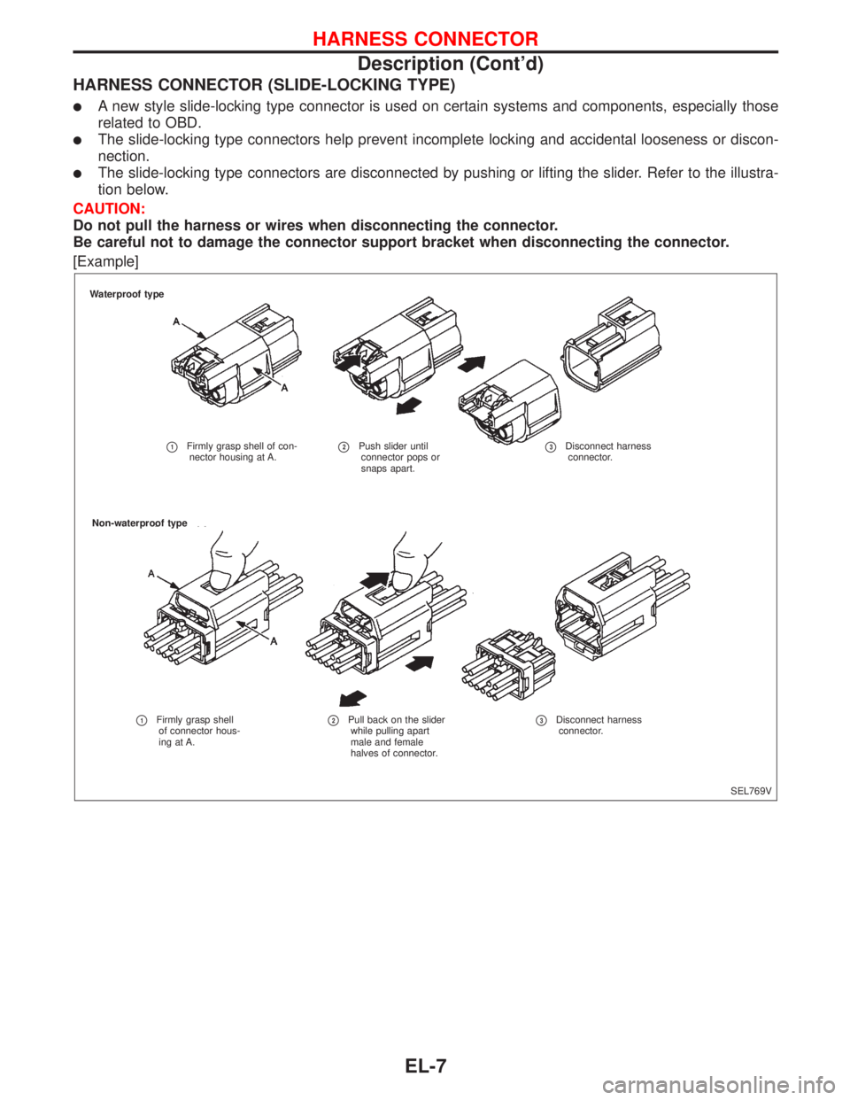
HARNESS CONNECTOR (SLIDE-LOCKING TYPE)
�A new style slide-locking type connector is used on certain systems and components, especially those
related to OBD.
�The slide-locking type connectors help prevent incomplete locking and accidental looseness or discon-
nection.
�The slide-locking type connectors are disconnected by pushing or lifting the slider. Refer to the illustra-
tion below.
CAUTION:
Do not pull the harness or wires when disconnecting the connector.
Be careful not to damage the connector support bracket when disconnecting the connector.
[Example]
SEL769V Waterproof type
�1Firmly grasp shell of con-
nector housing at A.�2Push slider until
connector pops or
snaps apart.�3Disconnect harness
connector.
Non-waterproof type
�1Firmly grasp shell
of connector hous-
ing at A.�2Pull back on the slider
while pulling apart
male and female
halves of connector.�3Disconnect harness
connector.
HARNESS CONNECTOR
Description (Cont’d)
EL-7
Page 1154 of 2267

Fuse
a. If fuse is blown, be sure to eliminate cause of problem before
installing new fuse.
b. Use fuse of specified rating. Never use fuse of more than
specified rating.
c. Do not partially install fuse; always insert it into fuse holder
properly.
d. Remove fuse for“ELECTRICAL PARTS (BAT)”if vehicle is
not used for a long period of time.
Fusible Link
A melted fusible link can be detected either by visual inspection
or by feeling with finger tip. If its condition is questionable, use
circuit tester or test lamp.
CAUTION:
�If fusible link should melt, it is possible that critical cir-
cuit (power supply or large current carrying circuit) is
shorted. In such a case, carefully check and eliminate
cause of problem.
�Never wrap outside of fusible link with vinyl tape.
Important: Never let fusible link touch any other wiring
harness or vinyl or rubber parts.
Circuit Breaker Inspection
For example, when current is 30A, the circuit is broken within 8
to 20 seconds.
Circuit Breaker (PTC Thermistor Type)
The PTC thermister generates heat in response to current flow.
The temperature (and resistance) of the thermister element var-
ies with current flow. Excessive current flow will cause the
element’s temperature to rise. When the temperature reaches a
specified level, the electrical resistance will rise sharply to con-
trol the circuit current.
Reduced current flow will cause the element to cool. Resistance
falls accordingly and normal circuit current flow is allowed to
resume.
CEL083 OK Blown
NEL545
FuseFusible link
SBF284E Time (sec.)
Break point
Current (A)
SEL109W
POWER SUPPLY ROUTING
EL-22
Page 1202 of 2267

Bulb Replacement
The headlamp is a semi-sealed beam type which uses a replace-
able halogen bulb. The bulb can be replaced from the engine
compartment side without removing the headlamp body.
�Grasp only the plastic base when handling the bulb.
Never touch the glass envelope.
1. Disconnect the battery cable.
2. Turn the bulb retaining ring counterclockwise until it is free
from the headlamp reflector, and then remove it.
3. Disconnect the harness connector from the back side of the
bulb.
4. Remove the headlamp bulb carefully. Do not shake or rotate
the bulb when removing it.
5. Install in the reverse order of removal.
CAUTION:
Do not leave headlamp reflector without bulb for a long
period of time. Dust, moisture, smoke, etc. entering head-
lamp body may affect the performance of the headlamp.
Remove headlamp bulb from the headlamp reflector just
before a replacement bulb is installed.
Aiming Adjustment
When performing headlamp aiming adjustment, use an aiming
machine, aiming wall screen or headlamp tester. Aimers should
be in good repair, calibrated and operated in accordance with
respective operation manuals.
If any aimer is not available, aiming adjustment can be done as
follows:
For details, refer to the regulations in your own country.
a. Keep all tires inflated to correct pressures.
b. Place vehicle and tester on one and same flat surface.
c. See that there is no-load in vehicle (coolant, engine oil
filled up to correct level and full fuel tank) other than the
driver (or equivalent weight placed in driver’s position).
CAUTION:
Be sure aiming switch is set to“0”when performing aiming
adjustment on vehicles equipped with headlamp aiming
control.
SEL995K Rubber
capOpenBulb cover
Lock
Push
to
remove
SEL466V
HEADLAMP (without Daytime Light System)—Conventional Type—
EL-70
Page 1223 of 2267

System Description
The auto level control unit is designed to adjust the beam angle of the headlamp in response to the load-
ing conditions of the vehicle. It is not designed to compensate for the dynamic handling of the vehicle.
The vehicle’s front and rear height is measured by sensors attached to the front stabilizer bar and the rear
suspension lateral link arm. The sensors provide a signal to the auto level control unit, which calculates the
correct headlamp aiming position and sends a signal to the aiming motors.
Initialisation
After the replacement or adjustment of any suspension sensor, the system must be self calibrated. This is
achieved as follows.
The vehicle must be empty, since any load will result in an invalid calibration. From outside of the vehicle
turn ignition on and then within 7 seconds the light switch must be turned from off to side lights on position,
5 times, finishing with the lamps in the on position.
The headlamps will then move to the highest, then the lowest then the normal position to indicate that the
calibration is successful, as can be seen by the moving beam pattern.
After successful calibration the headlamps must then be aimed in the conventional manner. Refer to EL-70.
HEADLAMP—Headlamp Aiming Control (Auto)—
EL-91
Page 1370 of 2267
 refer to terminal Nos. arranged in order when the UP or DOWN section
of power window switch is pressed.
Operation by main switch
Power is supplied
�throug")
REAR DOOR RH
NOTE:
Figures in parentheses ( ) refer to terminal Nos. arranged in order when the UP or DOWN section
of power window switch is pressed.
Operation by main switch
Power is supplied
�through power window main switch (�15,�16)
�to rear power window sub-switch RH (�3,�1).
The subsequent operations are the same as those outlined under“Operation by sub-switches”.
Operation by sub-switches
Power is supplied
�through rear power window sub-switch RH (�2,�4)
�to rear power window regulator RH (�1,�2).
Ground is supplied
�to rear power window regulator RH (�2,�1)
�through rear power window sub-switch RH (�4,�2)
�to rear power window sub-switch RH (�1,�3)
�through power window main switch (�16,�15)
Then, the motor raises or lowers the window until the switch is released.
AUTO OPERATION
The power window AUTO feature enables the driver to open or close the driver’s window without holding
the window switch in the respective position.
When the AUTO switch in the main switch is pressed and released, the driver’s window will travel to the
fully open or closed position.
POWER WINDOW LOCK
The power window lock is designed to lock-out window operation to all windows except the driver’s door
window.
When the lock switch is pressed to lock position, ground of the passenger side switch, rear RH switch and
rear LH switch in the power window main switch is disconnected. This prevents the power window motors
from operating.
POWER WINDOW
System Description (Cont’d)
EL-238
Page 1389 of 2267
Before starting trouble diagnoses below, perform preliminary check, EL-256.
Symptom numbers in the symptom chart correspond with those of Preliminary check.
SYMPTOM CHART
REFERENCE PAGE EL-258 EL-259 EL-260 EL-261 EL-262 EL-263
SYMPTOM
Power supply and ground circuit check
Procedure 1
(Door unlock sensor check)
Procedure 2
(Door key cylinder switch check)
Procedure 3
(Door lock actuator check)
Procedure 4
(Door switch check)
Procedure 5
(Key switch check)
1Power door lock does not operate
using any switch.XX
2Power door lock does not operate
with lock/unlock switch.X
3Power door lock does not operate
with door key cylinder switch.X
4Specific door lock acutator does
not operate.X
5*Key reminder system does not
operate.XX
X: Applicable
*: Make sure the power door lock and key reminder system operate properly.
POWER DOOR LOCK
Trouble Diagnoses (Cont’d)
EL-257
Page 1416 of 2267

Before starting trouble diagnoses below, perform preliminary check, EL-283.
Symptom numbers in the symptom chart correspond with those of Preliminary check.
SYMPTOM CHART
REFERENCE PAGE EL-285 EL-286 EL-287EL-288,
289EL-290,
291EL-292,
293EL-294 EL-295 EL-295
SYMPTOM
Power supply and ground circuit check
Procedure 1
(Door unlock sensor check)
Procedure 2
(Door key cylinder switch check)
Procedure 3
(Door lock actuator check)
Procedure 4
(Super lock actuator check)
Procedure 5
(Door switch check)
Procedure 6
(NATS release signal check)
Procedure 7
(Key switch check)
Procedure 8
(Ignition switch“ON”circuit check)
1Power door lock does not operate
using any switch.XX X
2Power door lock does not operate
with any switch of driver side.X
3Power door lock does not operate
with any switch of passenger side.XX
4Specific door lock acutator does
not operate.X
5Super lock cannot be set by both
door key cylinders.XXX XX
6Super lock cannot be set by one of
door key cylinders.X
7*Super lock cannot be released by
one or both door key cylinders.X
8*Super lock cannot be released by
ignition key switch. (Signal from
NATS IMMU)X
9Specific super lock actuator does
not operate.X
10*Key reminder system does not
operate.XX
X: Applicable
*: Make sure the power door lock and key reminder system operate properly.
POWER DOOR LOCK—Super Lock—
Trouble Diagnoses (Cont’d)
EL-284